 Leta
Assembly
An assembly is a document of its own that places parts and sub-assemblies with mates and joints, runs them as mechanisms, and keeps the bill of materials. Its tabs are Assembly, Mechanism, Routing, Analysis and View.
Components
Parts and sub-assemblies go in rigid or flexible, nested to any depth, and a part inside a sub-assembly is worked on as a part.
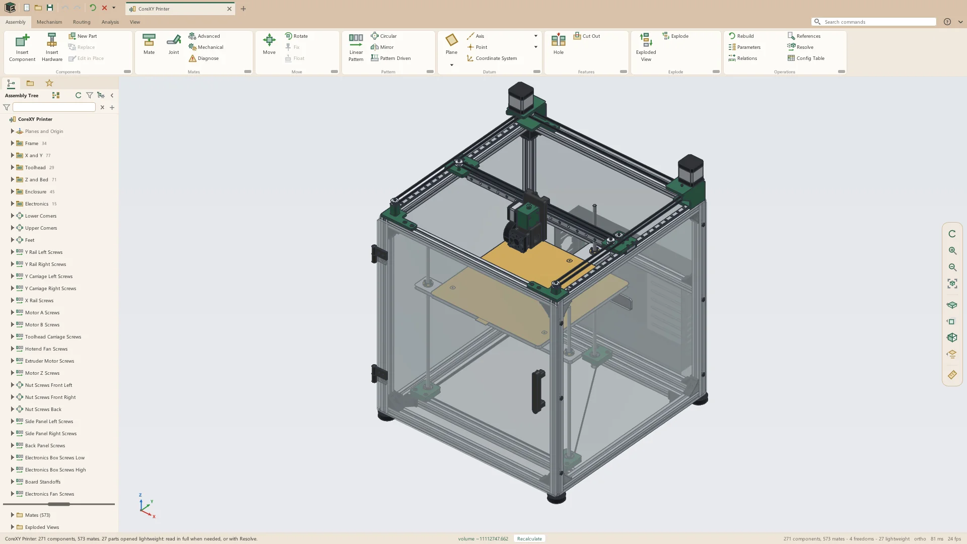
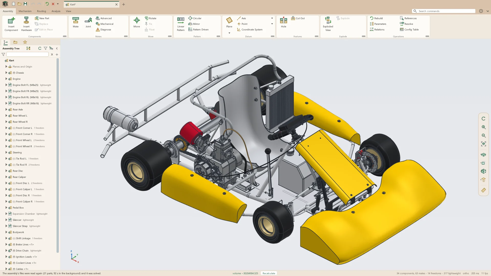
- Insert parts and sub-assemblies in the configuration wanted
- New Part placed on a clicked face, corner, hole or coordinate system, its first sketch open there
- Edit in Place, with sketches that take other parts' edges
- Replace a component, its mates finding their references again
- Place Again and Duplicate
- Components already placed saved as a sub-assembly with their mates
- Move and rotate within what the mates allow; the freedoms left shown in the tree
- Groups in the tree, and a flowchart of components and their mates
Mates
Mates go to faces, edges, points, datums and a part's own origin and coordinate systems, each with a flip. A broken or conflicting mate is named, and a lost reference is offered the nearest one like it.
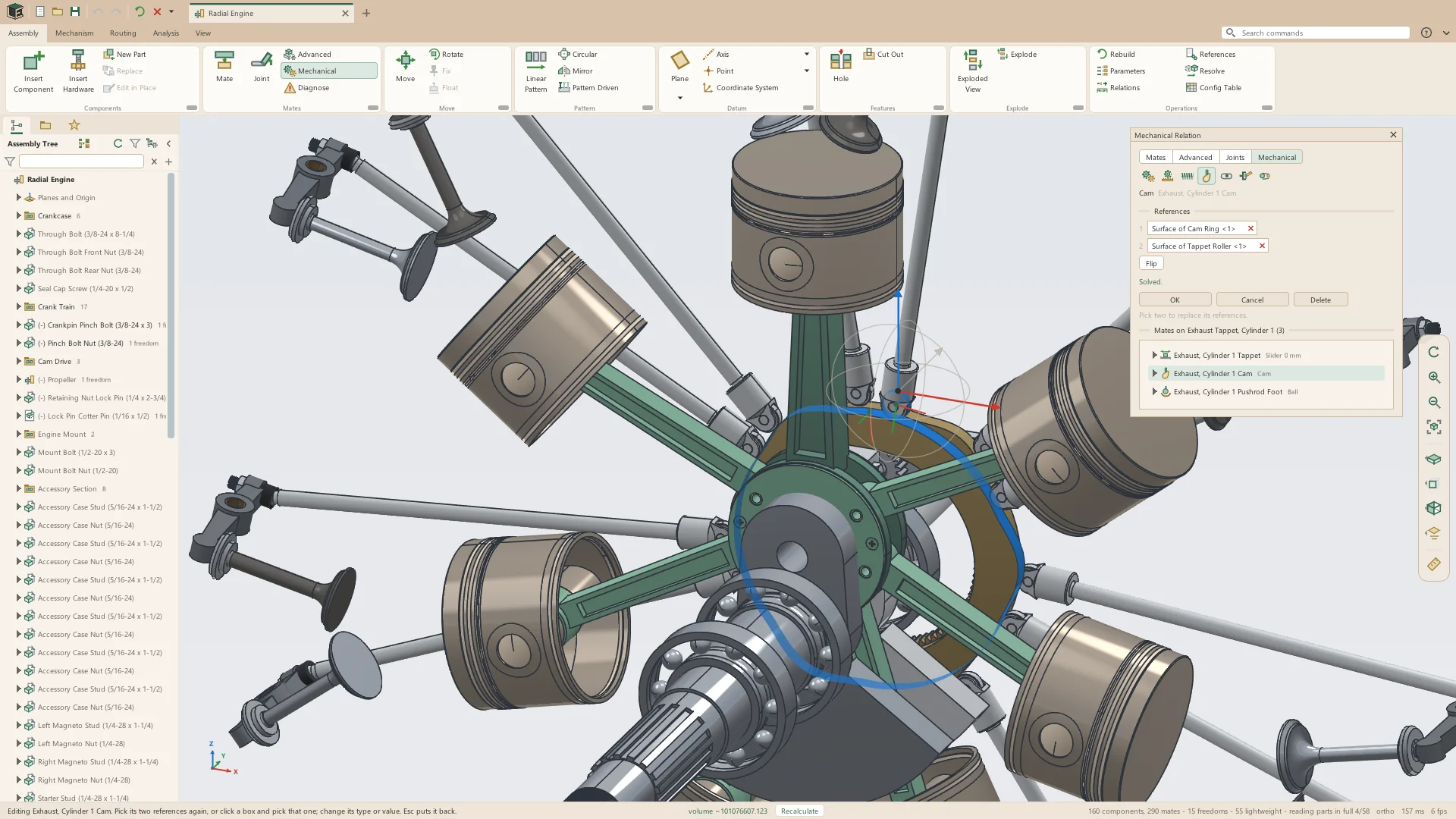
- Coincident, parallel, perpendicular, tangent, concentric, distance, angle and lock
- Symmetric, width, profile center, path and linear coupler
- Hole Pattern: a part held by its mounting holes
- Ctrl+click two parts for a menu of the mates that fit
- Diagnose lists conflicting and broken mates
- Parameters, relations and units of the assembly's own
Mechanisms and motion
Joints and couplings make an assembly move as the real machine does. Drag a part and the mechanism follows; drive a joint with a motor and run a motion study.
- Joints: fastened, revolute, slider, cylindrical, ball, planar and pin slot, with limits
- Couplings: gears, rack and pinion, screws, cams, slots, universal joints and belts
- Drag a part and the mechanism follows, with collisions highlighted
- Motion studies: motors drive joints over time, stopping at a collision if asked
- Plots of one joint against another or against time, saved as CSV
- Section views that follow the parts as they move
Exploded views
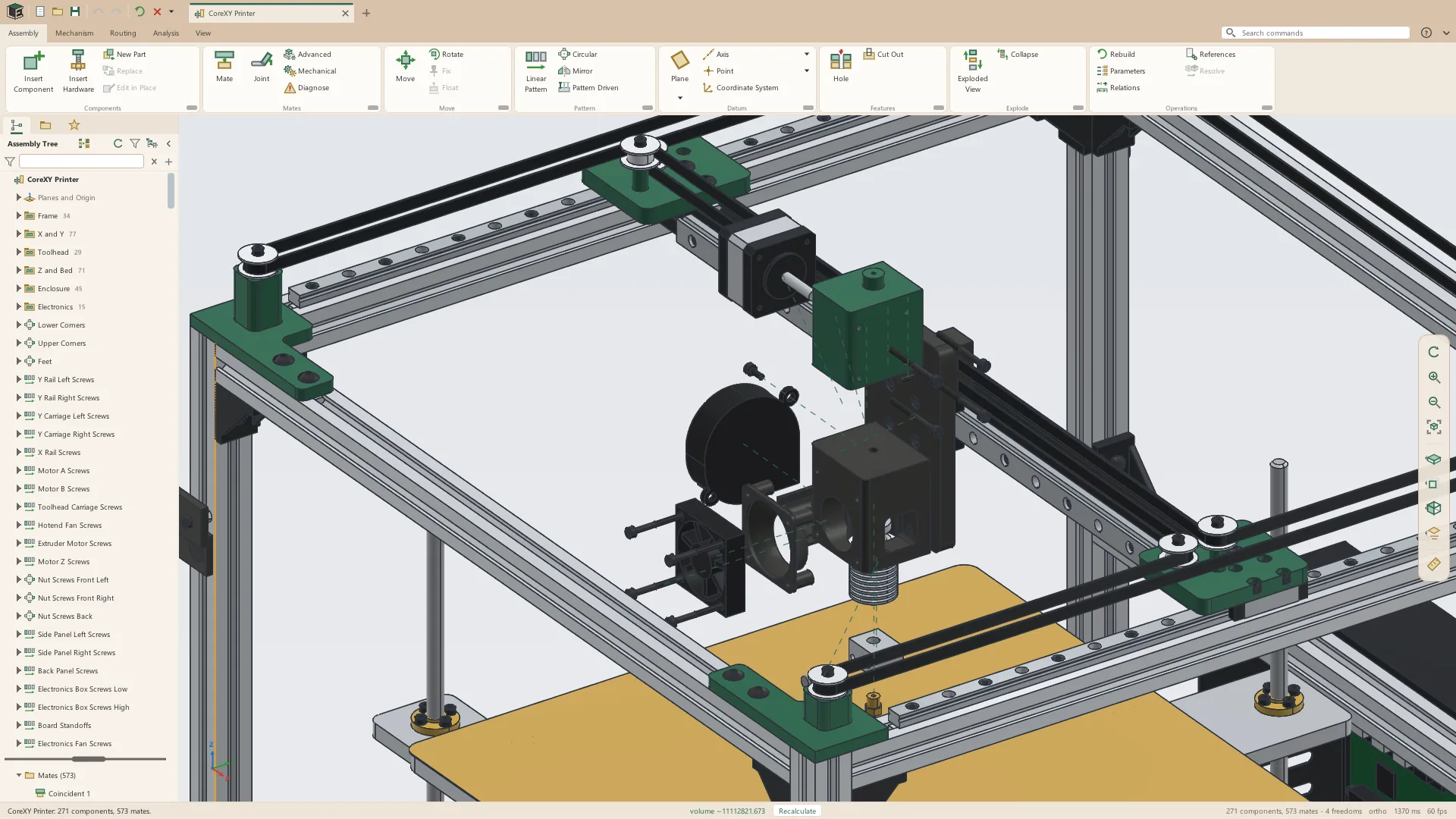
An exploded view is a list of steps that move or turn parts, with dashed trails back to where they came from. Explode and Collapse play the steps in turn, and drawings show them.
Belts and chain
A belt is laid round pulleys clicked in the order it runs, closed or with its ends clamped to a carriage, and then drives them. Roller chain sits in the sprockets' teeth in whole links.
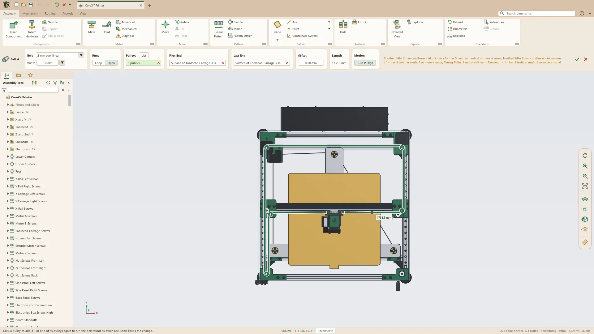
- Timing belts in eight pitches, flat belts and round belts
- The belt's length and tooth count, and the pulleys and carriages it drives
- Roller chain in ANSI and ISO sizes, its rollers in the sprocket teeth
- Chain in whole links, with the slack and how far to move a sprocket
Routing
Pipe, tube, hose and cable run out of ports and through holes along their axes, kept in a route assembly beside the main one, and are laid again when the parts they pass through move.
- Pipe in Schedules 10, 40 and 80 with long-radius elbows, and a cut list
- Bent tube with a bend table for the bender
- Hose and cable, with the tightest bend shown and Relax to ease a hose
- Wire harnesses: connectors with named pins, bundles with breakouts, and a wire list in and out as CSV
Hardware library
Insert Hardware places standard parts from a library of 101 families in metric and inch sizes, compiled from manufacturers' and distributors' published catalogs. One click on a hole's edge seats a screw, nut, washer, bearing or pulley.
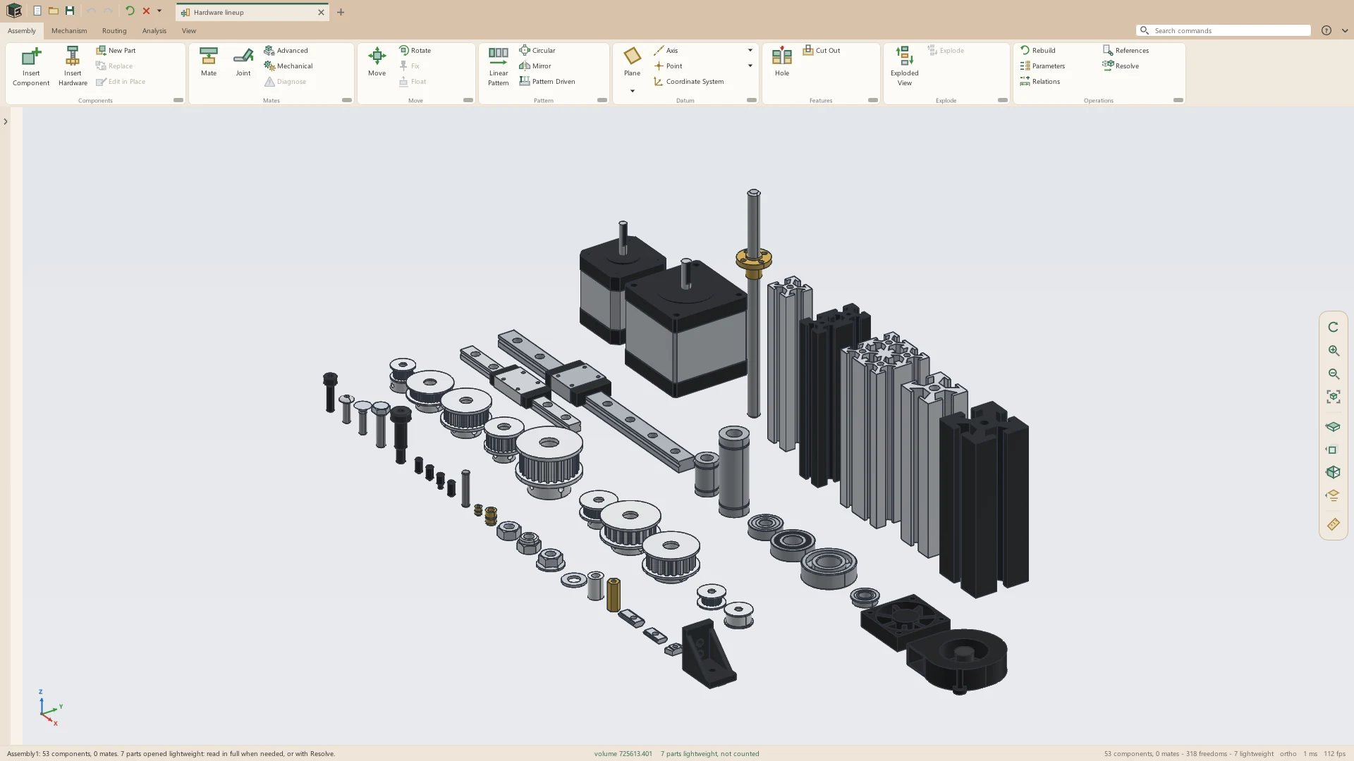
- Screws, nuts, washers, pins, keys, retaining rings, rivets, inserts, spacers and standoffs
- Timing pulleys, idlers and roller chain sprockets
- Ball bearings, bushings, linear shafts, rails and lead screws
- Stepper motors, fans and blowers
- T-slot extrusion, T-slot nuts and corner brackets
- Change Hardware swaps size, style or material and keeps the mates
Patterns and assembly features
- Linear and circular component patterns
- Pattern Driven: bolts placed in every hole of a part's own pattern
- Mirror, with true opposite-hand parts
- Datum planes, axes, points and coordinate systems of the assembly's own
- Holes through several parts at once, and Cut Out, kept in the assembly or written into the parts
Checks and the bill of materials
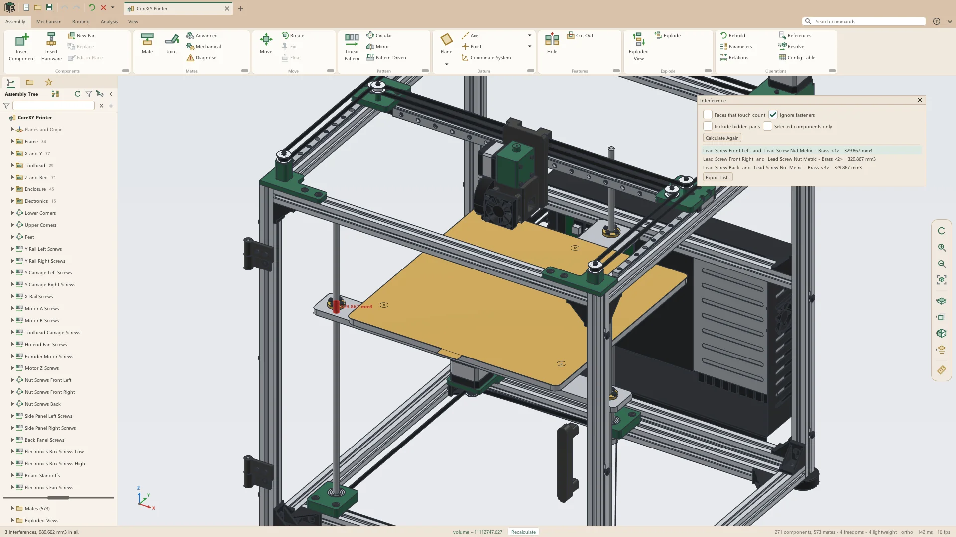
- Interference and clearance checks
- Measure and mass properties, each part weighed by its own material
- Section views, each part's cut face hatched, saved in the tree
- Bills of materials, top level, parts only or indented, to CSV or Excel
- STEP, STL, 3MF, OBJ and IGES export, and Pack and Go
Large assemblies
Each part carries its own picture and mass properties, so an assembly of hundreds of parts opens, draws, weighs and solves in seconds without building them.
- Partial Reps: each component complete, lightweight, left out, or replaced by a box, a simpler picture or another part
- Display states: which parts are shown, how see-through and what color
- Config tables: components in or out, part files swapped, mate values and sub-assembly configurations, a column each
- Drags solved in the background
See it on your own parts
Beta builds go out by email. Say what you design and what you use now.