 Leta
Drawing
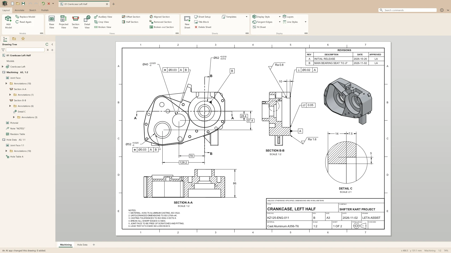
A drawing is a document of its own, in a window of its own, with Layout, Annotate, Sketch and Publish tabs. Its views stay tied to the part or assembly they show, and its dimensions and notes follow the model when it changes.
Sheets of drawings
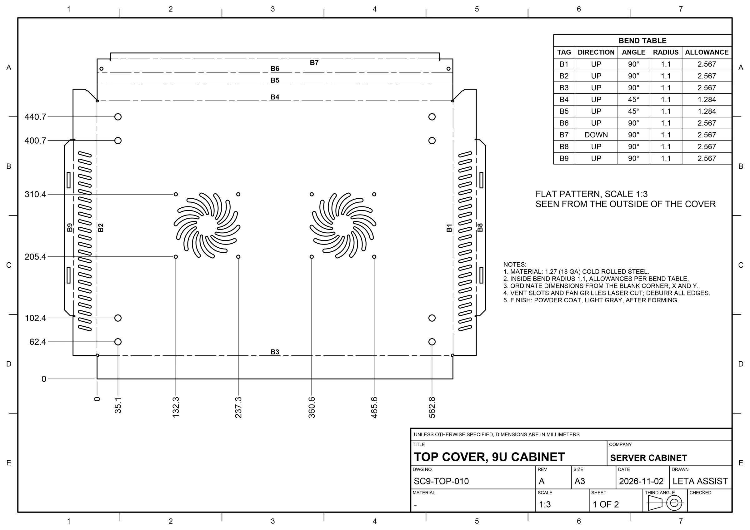
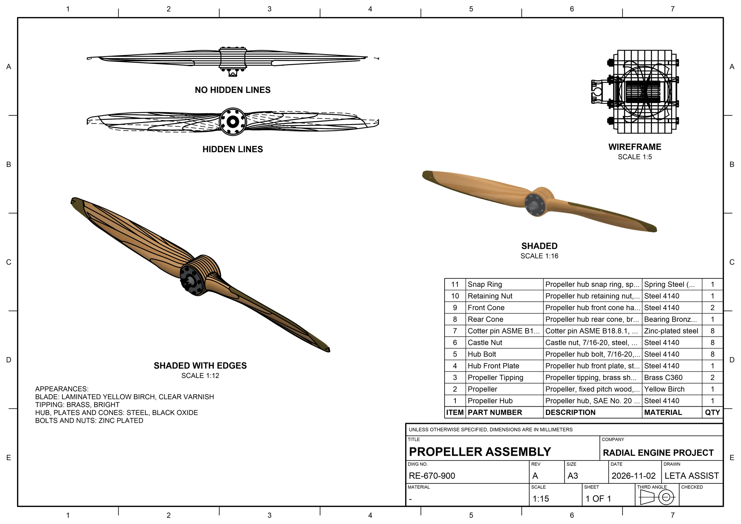
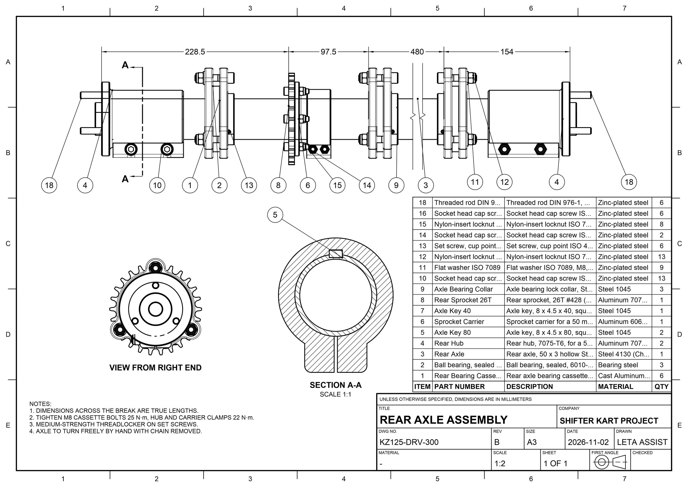
A new drawing of a part starts with its front, top and right views and a pictorial laid out on the sheet; a sheet-metal part also gets a sheet with its flat pattern and bend table. The drawings below were made in Leta by an AI app through Leta Assist and exported as they are. Each opens full size, and its PDF is linked under it.
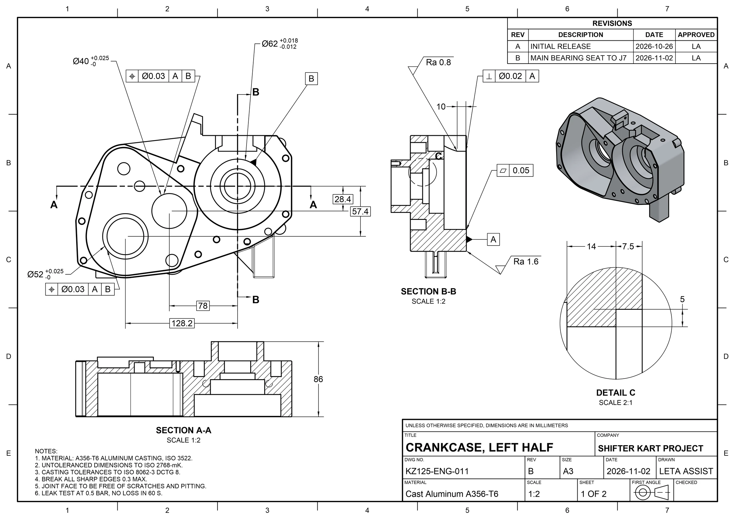
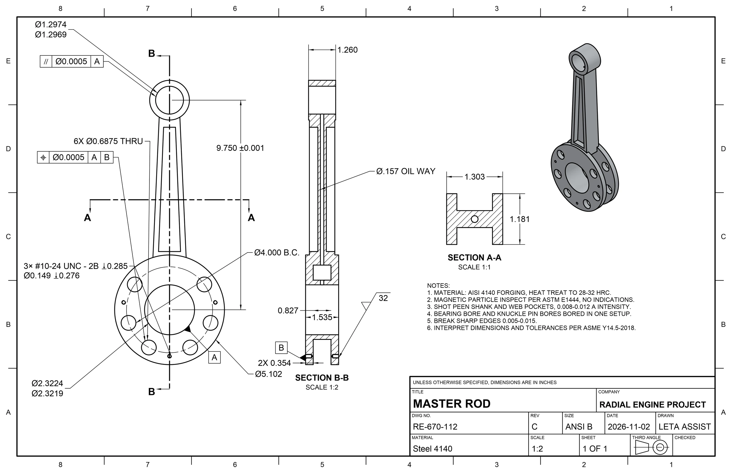
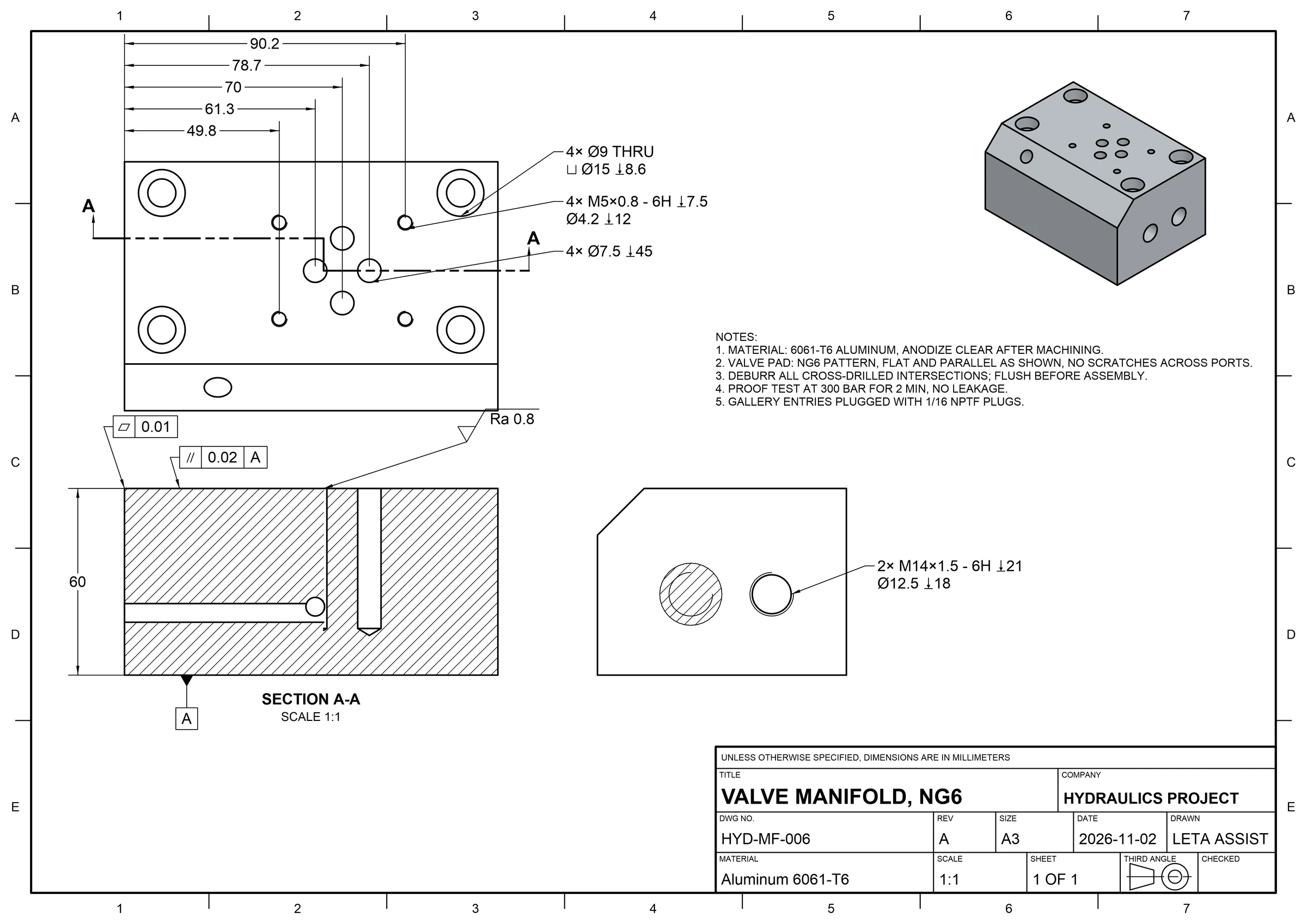
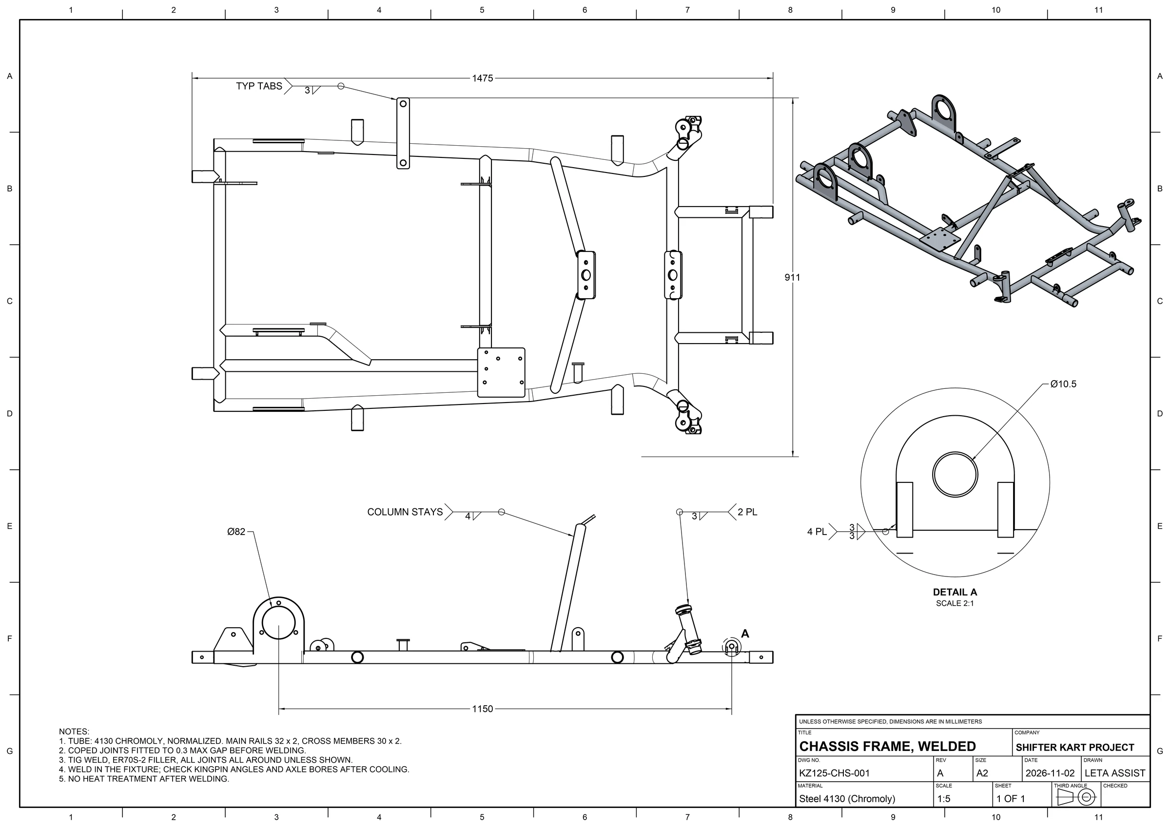
Views and sections
Hidden lines are worked out exactly, in the background, and edges stay tied to the model's own edges, so a dimension on a view keeps its place when the part changes.
- Base, projected and pictorial views
- Full, offset, half, aligned, removed and broken-out sections, hatched
- Sections cut in place by a plane, or by a sketch for a stepped cut
- Detail, auxiliary, cropped and broken views
- Shading with edges, shading in the model's appearances, hidden line, no hidden and wireframe
- Tangent edges solid, thin or removed
- Views turned on the sheet, scales typed as 1:3, 2.5:1 or 1/20
- Any configuration of a part, view by view
- Flat pattern views with bend notes
- Draft views for very large models
Dimensions and annotation
Dimensions, callouts and symbols are placed on the model's edges and points, and anything that loses its reference is listed in red, never moved without saying so.
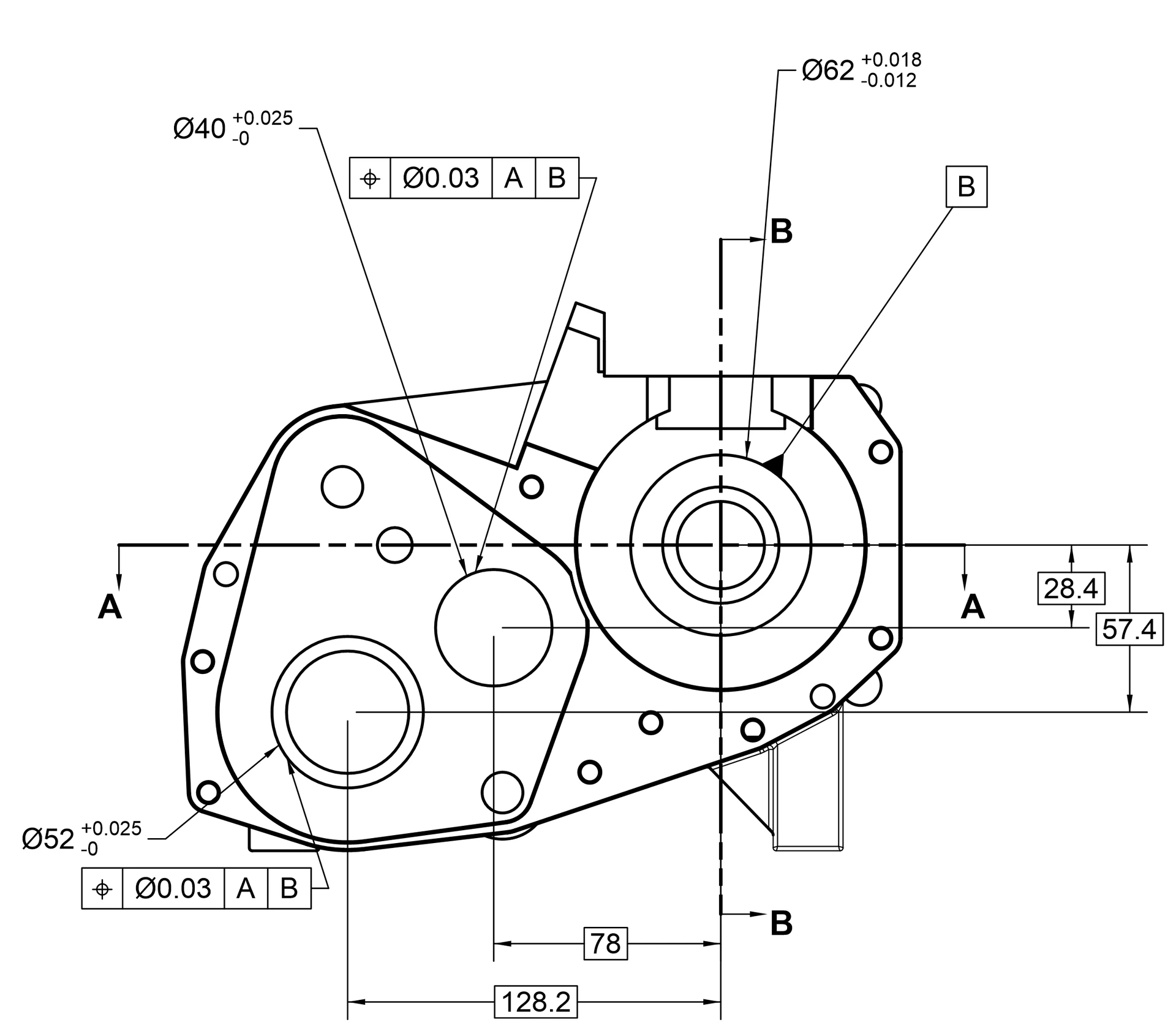
- One Dimension tool, and ordinate, baseline and chain dimensions with Arrange
- Tolerances: symmetric, plus-minus, limits and basic
- Hole, thread, chamfer and round callouts and center marks from the model
- Threads drawn by convention
- Feature control frames with all fourteen characteristics, and datum features
- Surface finish and weld symbols
- Notes with several leaders, balloons and revision clouds
- Dimensions and notes on the lines a section cuts
Tables
Tables read the model, so a bill of materials, a hole table or a bend table changes with it.
- Bills of materials, flattened, top level or nested, numbered to match the balloons
- Hole tables and bend tables
- Revision tables
- Config tables, for a tabulated drawing of a part's sizes
Drawings of assemblies
An assembly drawing shows each view in the configuration or representation chosen for it, with item numbers that match the bill of materials.
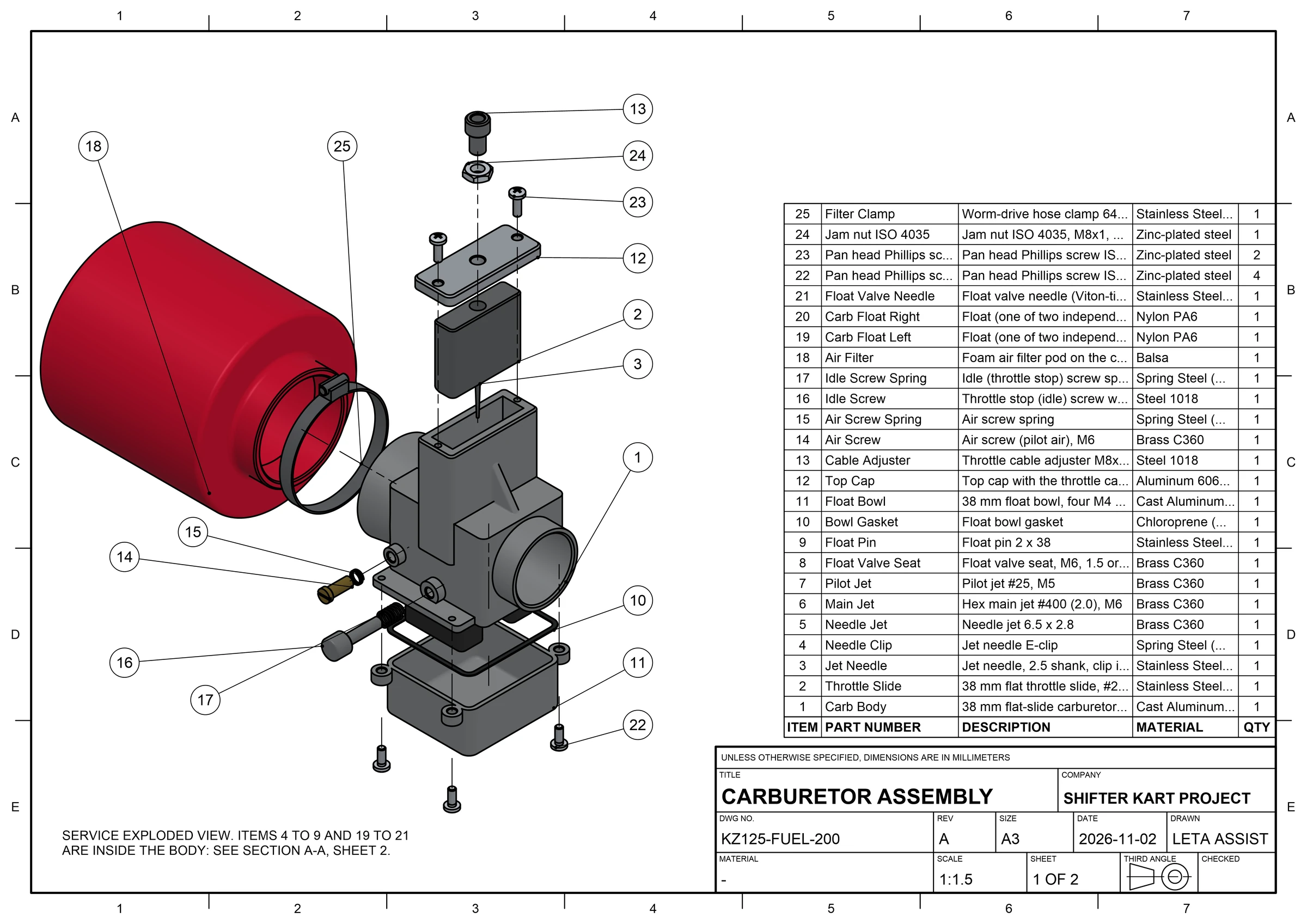
- Exploded views with their trails
- Balloons and item numbers tied to the bill of materials
- A configuration or a partial representation for each view
- Sections of assemblies, each part hatched on its own
Sheets, templates and line styles
Drawings follow a company's own standards: its title block, its layers and its line weights.
- ISO A4 to A0, ANSI A to E and custom sheet sizes; first- or third-angle projection
- Templates with a company's own title block, whose fields fill themselves
- A title block layout editor that splits, joins and moves cells, and holds a logo
- Layers, and line styles for whole kinds of line or single lines
- Hatch patterns, ISO 128 and the ANSI material symbols among them, in sections or any closed area
- Lines, arcs, splines, polygons and slots sketched on a view or the sheet, with offset, trim, mirror, fillet and chamfer
Publishing
Drawings go out at true scale.
- PDF, with searchable text
- DXF, R2000 or R12
- SVG
- PNG at 96 to 600 dpi
- Printing
See it on your own parts
Beta builds go out by email. Say what you design and what you use now.