 Leta
Mechanisms and motion
Joints leave parts free to move the way the real machine does, and couplings tie one joint's motion to another's. A mechanism can be dragged through its range by hand, or driven by motors in a motion study that is plotted, checked for collisions and recorded frame by frame.
Joints and limits
A joint holds two parts together and leaves free only the motion the real connection allows. Each of its freedoms can be limited, held at a typed value or let go, and the joint can be made where the parts already stand so that nothing moves.
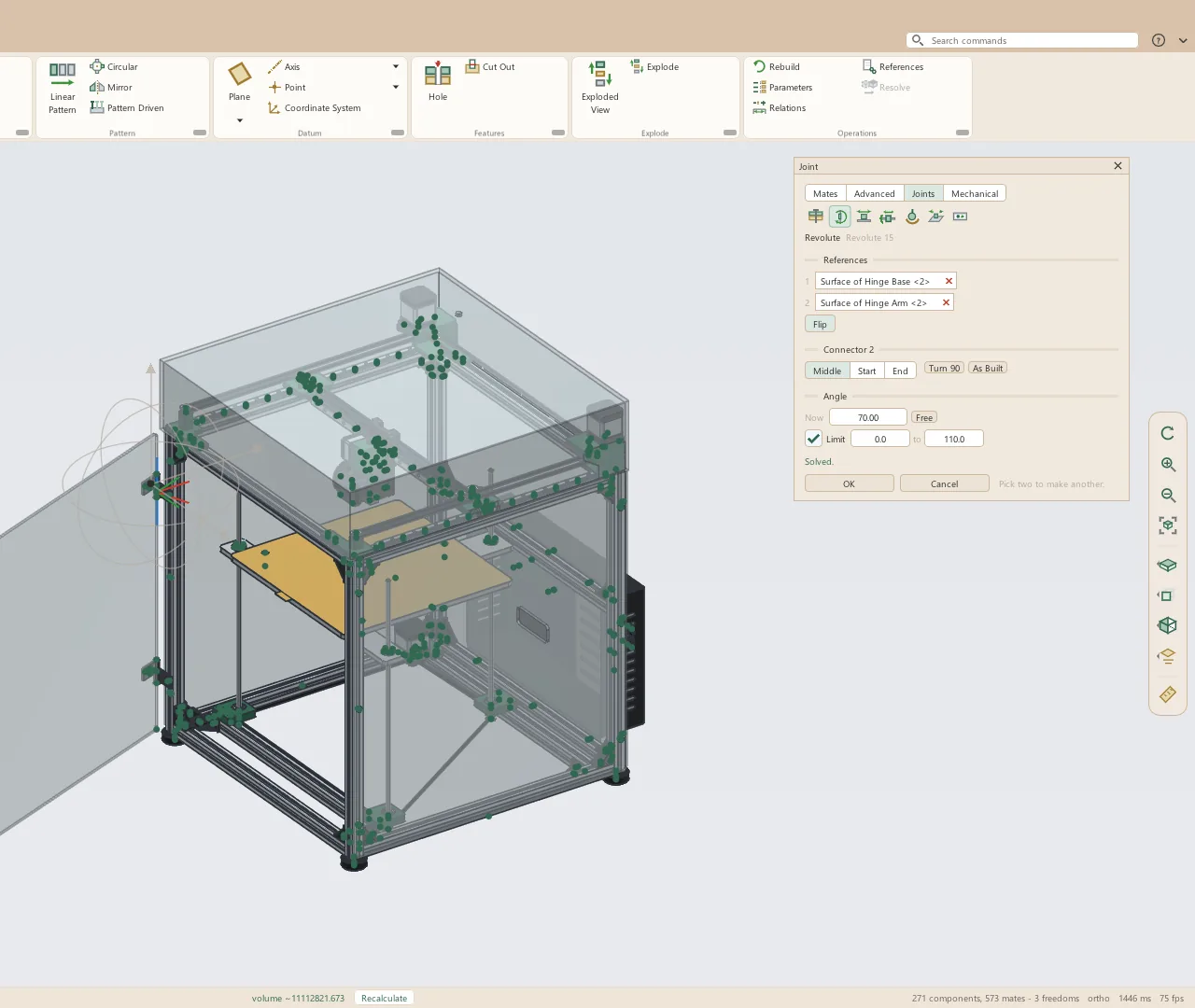
- Fastened, Revolute, Slider, Cylindrical, Ball, Planar and Pin Slot
- Each freedom's angle or travel shown as it stands: drag it, or type a value to move the parts there
- A typed value holds the joint until Free lets it move again
- Limit: a minimum and a maximum the joint stops at
- Distance and Angle mates limited between a minimum and a maximum the same way
- As Built makes the joint where the parts stand, its values reading zero there
- Joint values listed in the tree's Mates folder
- Limits and held values typed as numbers, parameters or expressions
Couplings
The Mechanical mates on the Mechanism tab tie one motion to another, and they work both ways: turning either gear of a pair turns the other.
- Gear: a ratio, the second gear's turns for each turn of the first
- Rack and Pinion: the pinion's pitch radius, the rack moving 2π times it each turn
- Screw: a lead, how far the nut moves each turn
- Cam: a follower held on a cam's outline, as a point, a roller or a ball
- Slot: a pin held in a slot
- Universal Joint: two shafts at an angle turning together
- Belt: pulleys or sprockets turned together, each by its own size
- Linear Coupler, among the Advanced mates: two slides moving at a ratio
Dragging and collisions
A part dragged with the mouse moves as far as its joints and mates let it, and everything joined to it follows. The drag can light the parts that run into each other, or stop where they would.
- Any part dragged with the left button, the mechanism following within its joints
- A move triad on the selected part, the directions its mates hold grayed out and naming what holds them
- Parts fastened to the dragged part move with it as one
- Only the parts that can move are solved, in the background while the window keeps drawing
- Highlight lights every part that runs into another while dragging
- Stop at Collision stops the drag where the part would run into another
- Parts already fitted together, such as a shaft in its bore, are passed over
- Highlight Collisions turns itself off when it would hold a drag under 20 frames a second, says so, and offers to turn back on
Freedoms
Leta works out how many ways each part can still move from the mates and joints that hold it. The count shows in the tree, and the ways themselves on the model.
- Freedoms, on the Mechanism tab, draws an arrow or a turn on the selected part for each way it can still move
- The tree marks each component fixed, floating, over-defined, or with the number of freedoms it has left
- Diagnose names the fewest mates that conflict, and the mates the others make redundant
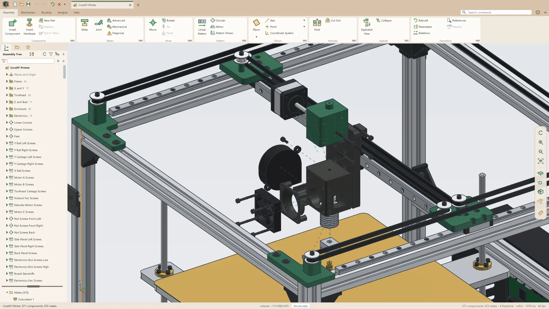
- The CoreXY printer sample is placed down to four freedoms: the head's X and Y, the bed's height and the door
Motion studies
A motion study drives joints with motors over time, works out every frame, and plays them back, naming the first collision and when it happens. It is kinematic: motors set joint values over time, with no forces or gravity.
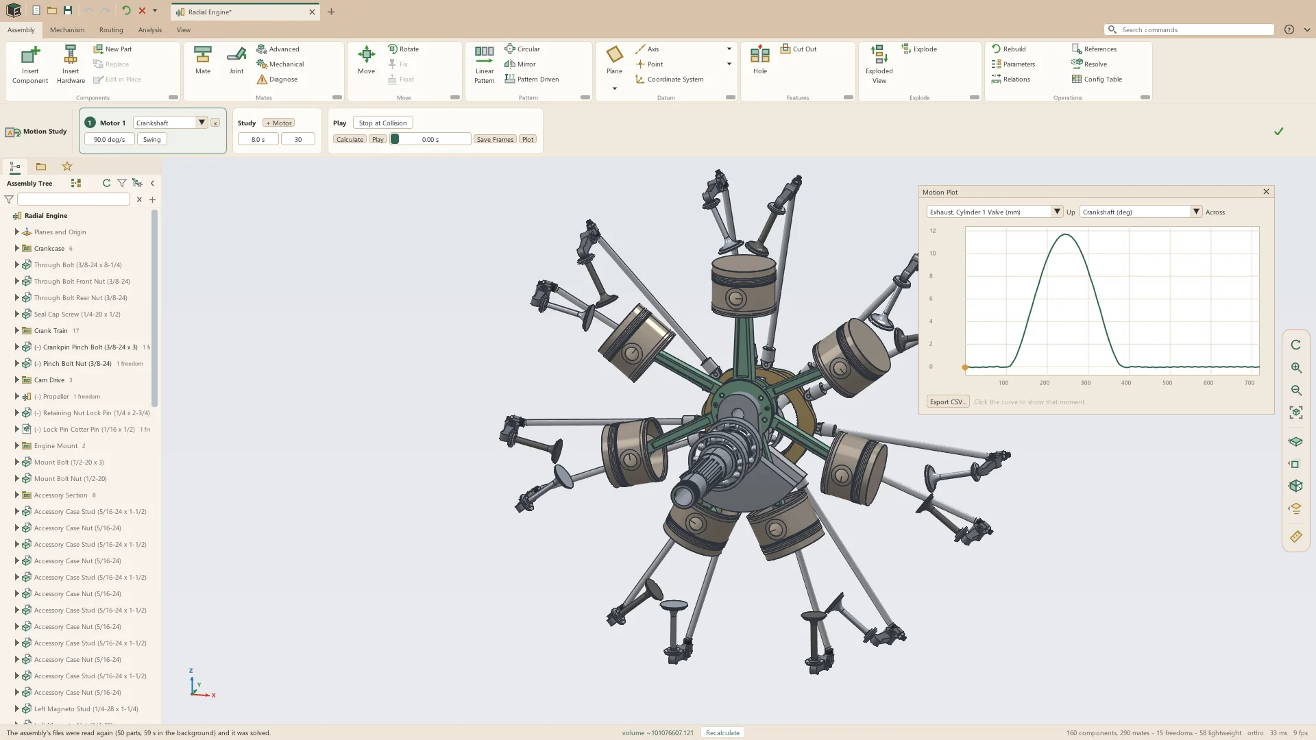
- As many motors as needed, each on a joint that turns or slides
- Each motor's speed in degrees or millimeters a second, as a number or an expression
- On a joint that both turns and slides, the turn or the slide driven
- Swing: back and forth between two values instead of on and on
- A length of up to 600 seconds, at 1 to 120 frames a second
- Calculate works out the frames and reports the first collision by time and by the two parts
- Stop at Collision ends the study where two parts first run into each other
- Play, Pause and a time slider to any moment
- Save Frames writes every frame of the graphics window into a folder as numbered pictures, for a video
- Done puts every part back where it was; the motors and settings are kept with the assembly
The radial engine
The seven-cylinder radial engine sample is a mechanism from end to end, driven by one motor on its crankshaft's joint. Its study turns the crankshaft at 90 degrees a second for 8 seconds: two turns, one whole four-stroke cycle.
- The crankshaft on a revolute joint in its bearings
- The master rod on the crankpin, and six link rods on its knuckle pins
- Seven pistons sliding in their bores, each turning on its pin
- Two Gear mates turn the cam ring at a sixth of the crankshaft's speed, the other way
- Cam mates lift each tappet's roller on its lobe track
- Pushrods on ball joints at both ends, and rockers on revolute joints
- Valves sliding in their guides, held tangent to the rockers' pads
- The valves open and shut with the engine's valve timing, in firing order
Sections that follow the parts
A section cuts every part of the assembly open on a plane, each part's cut face capped and hatched apart from its neighbor's. It follows every drag and every frame of a motion study, so the inside of a mechanism can be watched while it runs.
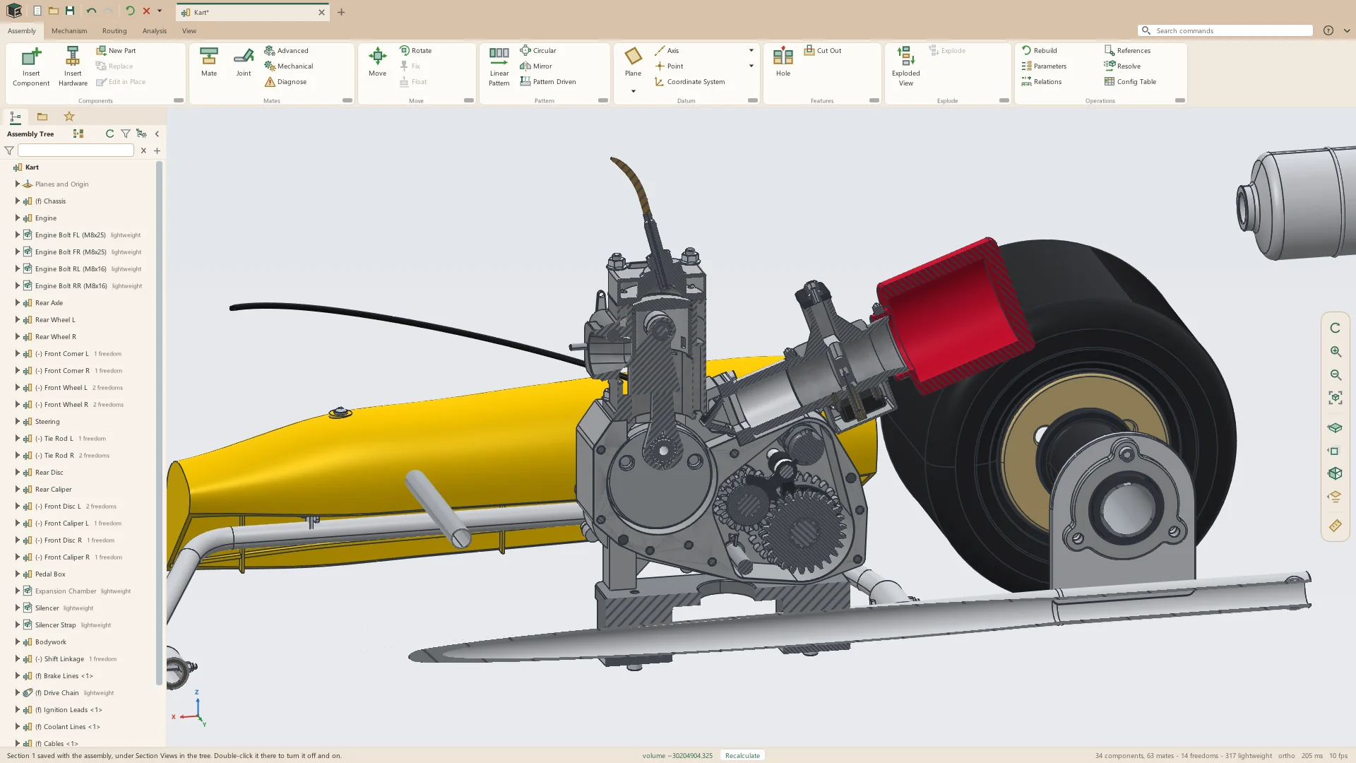
- Cut on the X, Y or Z direction, on a plane picked, or on the flat face or datum plane selected
- An offset, and Flip to keep the other side
- Each part's cut face colored and hatched differently from the next
- Shown at once in large assemblies, and cut again with every change and drag
- Saved with the assembly under Section Views in the tree, turned on and off by a double-click
- Save Frames with a section on records the cut as the parts move, for a video
Plots
A motion study records the value of every joint and relation at each frame. The Motion Plot draws any of them against another, or against time.
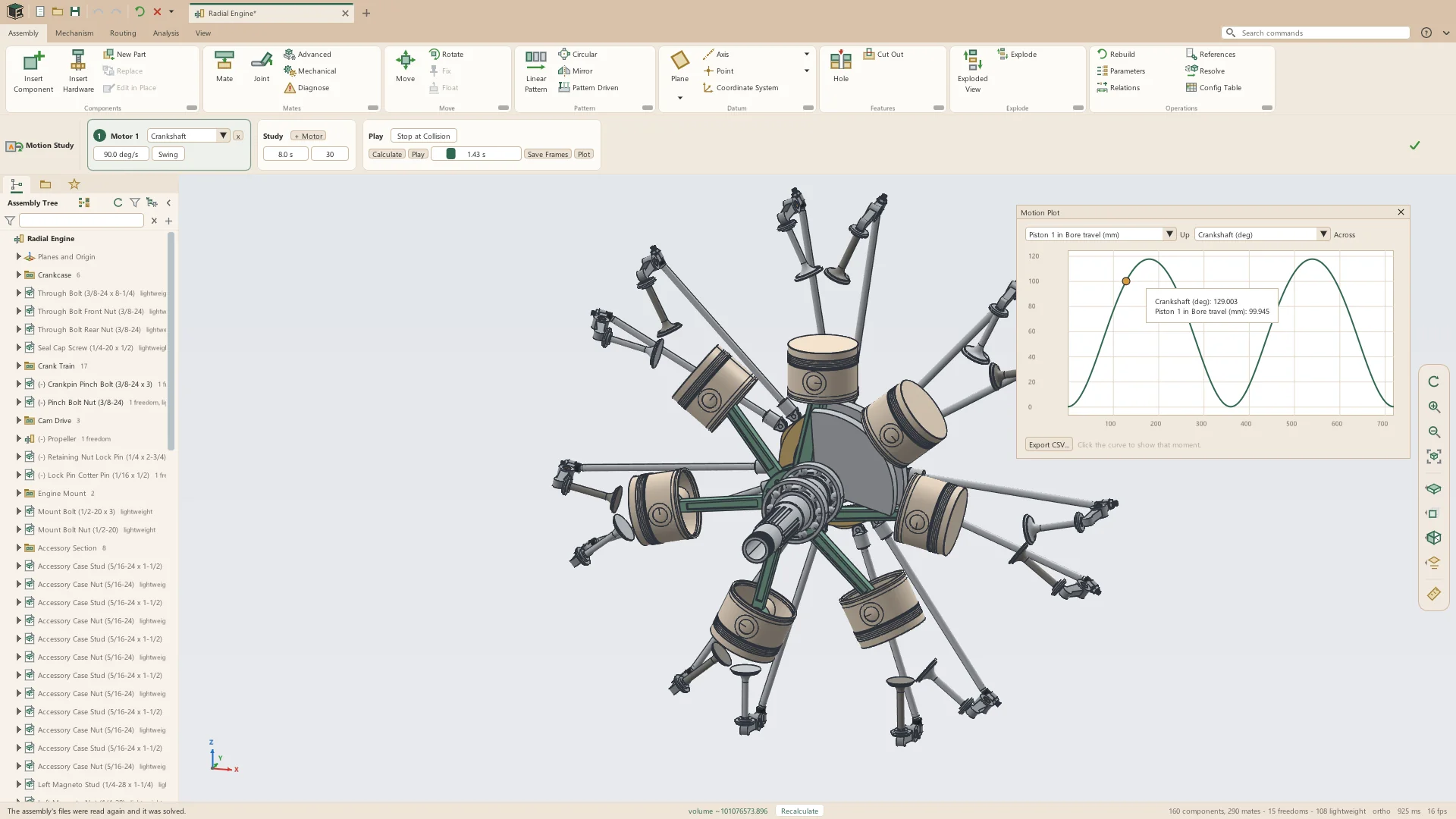
- Up and Across: any joint's angle or travel, or time
- The pointer on the curve reads both values there
- A click on the curve shows that frame on the model
- Export CSV: time and every joint's value, frame by frame
- Opened from Plot on the Mechanism tab or on the study's Play card
Exploded views
An exploded view is a list of steps, each sliding or turning a set of components, with trails back to where they stood. Explode and Collapse play the steps in turn, and drawings of the assembly can show the view.
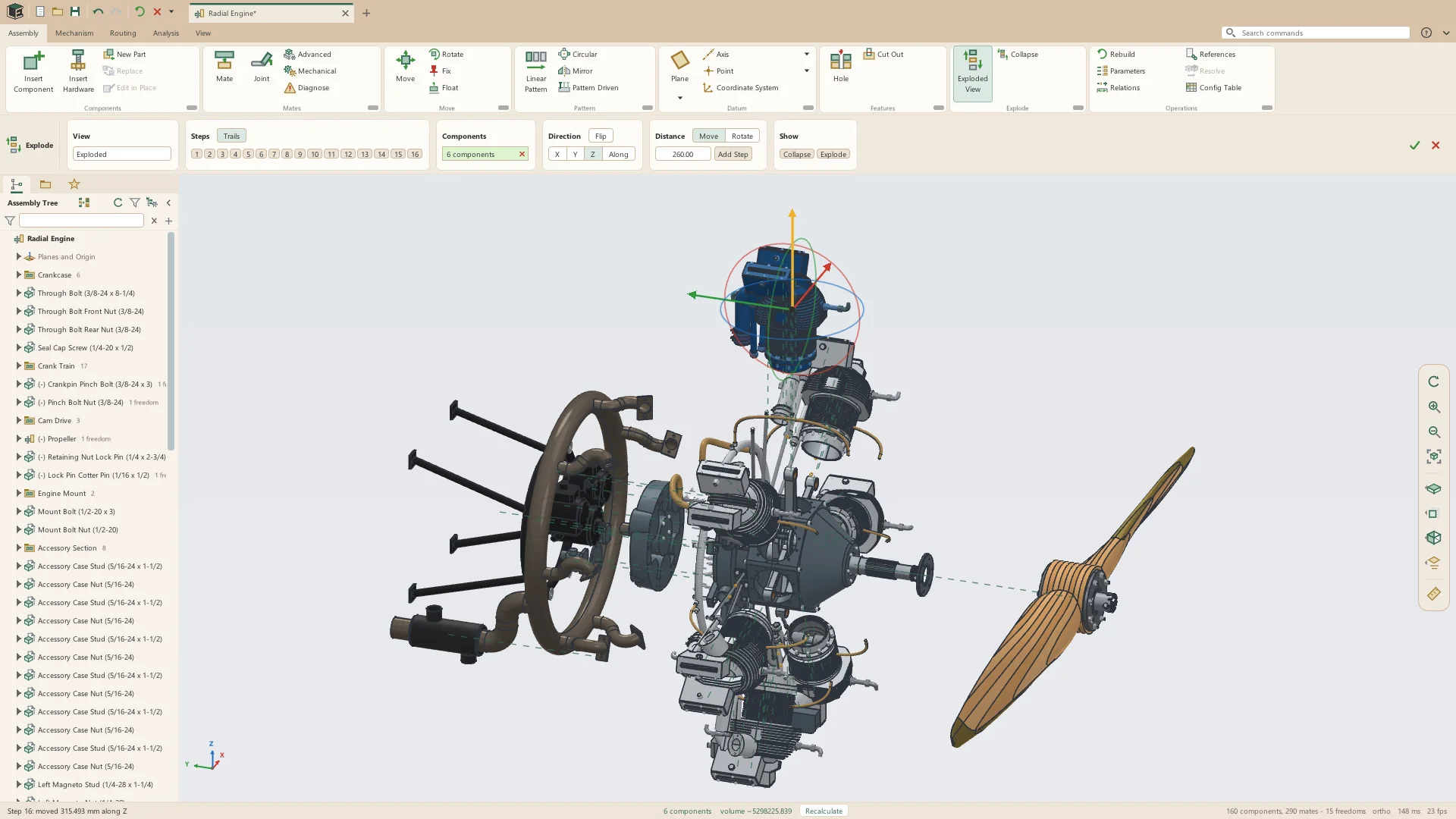
- Steps that slide components along the assembly's X, Y or Z, or along an edge, an axis, a face's normal or a datum
- Steps that turn components about the direction chosen, by an angle
- The move triad on a step's components: drag an arrow or a ring to make a step or change one
- Trails: dashed lines from where each part stood
- A pattern's copies follow their seed
- Several exploded views in one assembly, listed in the tree
- Explode and Collapse on the ribbon, animated
- Drawing views of the assembly shown exploded
See it on your own parts
Beta builds go out by email. Say what you design and what you use now.