 Leta
Hardware library
Insert Hardware places standard parts from a library of 101 families in metric and inch sizes, from screws and nuts to bearings, pulleys, rails, stepper motors and T-slot framing. Each piece is chosen from pictures and placed with a click, and pieces with moving parts can go in as assemblies of their real parts.
The library
Insert Hardware, beside Insert Component, holds 101 families in 14 kinds, compiled from manufacturers' and distributors' published catalogs and checked against a second source wherever there is one. Each family is an ordinary Leta part with a Config Table, made the first time it is used, each size added to it as a configuration.
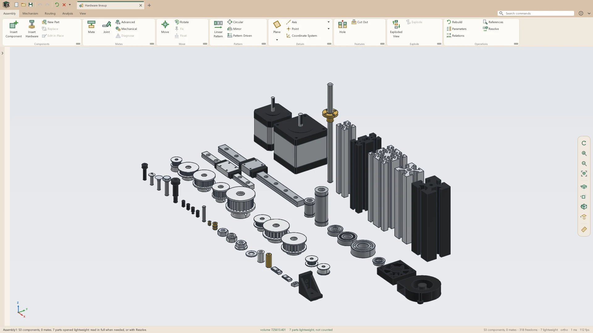
- Screw / Bolt, 16 families; Nut, 12; Washer, 7
- Spacer, Standoff and Insert, 4 families
- Pin / Clip, 8; Rivet, 2; Seal, 1
- Pulley, 20, sprockets among them
- Bearing, 8; Linear Motion, 11
- Motor / Fan, 3; Framing, 9
- Fasteners in steel, zinc-plated steel, black-oxide steel, 18-8 (A2) and 316 (A4) stainless steel, brass, aluminum and nylon
- One part file for each standard and material, kept in Documents\Leta\Hardware
Screws and bolts
Sixteen families of screws and bolts, each to its standard in metric and in inch sizes. Metric screws come in coarse and, where the standard has them, fine pitches; inch screws in UNC and UNF; each partly or fully threaded.
- Socket head cap screw: ISO 4762, M1.6 to M24; ASME B18.3, #0-80 to 1-8
- Low head socket cap screw: DIN 7984, M3 to M20; ASME B18.3, #6-32 to 1/2-13
- Button head socket screw: ISO 7380-1, M3 to M16; ASME B18.3, #0-80 to 5/8-11
- Flanged button head screw: ISO 7380-2, M3 to M12
- Flat head socket screw: ISO 10642, M2 to M20; ASME B18.3, #0-80 to 1-8
- Hex head screw: ISO 4017, M1.6 to M24; ASME B18.2.1, 1/4-20 to 1-8
- Hex flange screw: DIN 6921, M5 to M16; ASME B18.2.1, 1/4-20 to 5/8-11
- Carriage bolt: DIN 603, M5 to M16; ASME B18.5, #10-24 to 3/4-10
- Pan head and flat head Phillips machine screws: ISO 7045 and ISO 7046-1, M1.6 to M10; ASME B18.6.3, #0-80 to 3/8-16
- Set screws with cup, flat, cone and dog points: ISO 4029, 4026, 4027 and 4028, up to M12; ASME B18.3, #4-40 to 1/2-13
- Shoulder screw, named by its shoulder: ISO 7379, 4 to 16 mm; ASME B18.3, 1/4 to 3/4 in
- Threaded rod cut to any length: DIN 976-1, M3 to M24; ASME B18.31.3, #6-32 to 1-8
Nuts
Twelve families of nuts, metric and inch, in the same coarse, fine, UNC and UNF threads as the screws.
- Hex nut: ISO 4032, M1.6 to M24; ASME B18.2.2, #0-80 to 1-8
- Jam nut: ISO 4035, M1.6 to M24; ASME B18.2.2, #4-40 to 1-8
- Nylon-insert locknut and thin nylon-insert locknut: ISO 7040 and ISO 10511, M3 to M24; ASME B18.16.6, #2-56 to 1-8
- Flange nut: DIN 6923, M3 to M20; ASME B18.2.2, #6-32 to 3/4-10
- Flange nylon-insert locknut: DIN 6926, M4 to M20; inch #8-32 to 3/4-10
- Coupling nut: DIN 6334, M3 to M24; ASME B18.2.2, #6-32 to 1-8
- Acorn nut: DIN 1587, M3 to M24; inch #6-32 to 3/4-10
- Square nut: DIN 557, M5 to M16; ASME B18.2.2, #2-56 to 1-8
- Thin square nut, for nut traps: DIN 562, M1.6 to M10
- Knurled thumb nut: DIN 466, M1.6 to M12; inch #0-80 to 1/2-13
- Wing nut: DIN 315, M3 to M20; ASME B18.17, #4-40 to 1/2-13
Washers, spacers and inserts
Flat and lock washers to their standards, with round spacers, hex standoffs and heat-set inserts for printed parts. A spacer takes any length and a typed outside and inside diameter.
- Flat washer: ISO 7089, M1.6 to M24; SAE, #2 to 1 in
- Small flat washer: ISO 7092, M1.6 to M24
- USS flat washer: ASME B18.22.1, #10 to 1 in
- Large (fender) washer: ISO 7093-1, M3 to M24; inch #10 to 7/8
- Split lock washer: DIN 127, M2 to M24; ASME B18.21.1, #2 to 1 in
- Internal and external tooth lock washers: DIN 6797, M2 to M24; ASME B18.21.1, #2 to 1 in
- Round spacers for M2 to M10 and #2 to 3/8 screws, at any length
- Hex standoffs, female-female and male-female, M2 to M6 and 2-56 to 1/4-20
- Brass heat-set inserts for printed parts, M2 to M8 and #2-56 to 1/4-20
Pins, clips, rivets and seals
Pins, retaining rings, keys, blind rivets and O-rings, metric and inch. Keys are cut to any length, and rivets are shown set, the mandrel broken off in the head.
- Dowel pins: ISO 8734, 1 to 12 mm; ASME B18.8.2, 1/16 to 1/2 in
- Slotted spring pins: ISO 8752, 1 to 20 mm; ASME B18.8.2, 1/16 to 1/2 in
- Clevis pins: ISO 2341 B, 3 to 20 mm; ASME B18.8.1, 3/16 to 1 in
- Cotter pins: ISO 1234, 0.6 to 13 mm; ASME B18.8.1, 1/32 to 1/2 in
- Retaining rings: DIN 471 for 3 to 100 mm shafts and DIN 472 for 8 to 100 mm bores, and inch rings up to 2 in
- E-clips: DIN 6799, 1.2 to 30 mm; inch 1/8 to 1 in
- Parallel keys: DIN 6885 A, 2 × 2 to 28 × 16 mm; ASME B17.1, 1/16 to 1 × 3/4 in
- Blind rivets, dome head and countersunk: ISO 15977 and ISO 15978, 2.4 to 6.4 mm; IFI-114, 3/32 to 1/4 in
- O-rings in nitrile rubber: every AS568 dash number, -001 to -475, and the 378 sizes of ISO 3601-1
Pulleys and sprockets
Timing pulleys in eight belt pitches, idlers, and roller chain sprockets, each sized by its teeth. Belts and chain laid round them find their teeth by themselves.
- 2 mm curvilinear, 16 to 80 teeth, and 3 mm curvilinear, 20 to 60
- 3 mm and 5 mm round tooth, 15 to 40 teeth
- MXL, 11 to 60 teeth, and XL, 10 to 60
- T2.5, 12 to 60 teeth, and T5, 10 to 60
- Each pulley in the belt widths and bores it is sold in, aluminum or steel
- Toothed idlers with 16 and 20 teeth, and smooth idlers 9.5 to 16 mm across, for 2 mm belts
- Sprockets for #25, #35, #40, #41, #219 kart, #420, #428 and #520 chain and ISO 06B and 08B, steel or aluminum
- Sprockets from 9 to 60 teeth (the #219 to 90), their teeth drawn by the ANSI B29.1 proportions, each with a hub and a stock bore
Bearings and linear motion
Ball bearings, bushings, shafts, rails and lead screws for the moving parts of a machine. Rails, shafts and lead screws are cut to any length typed.
- Ball bearings, open, shielded (ZZ) and sealed (2RS): 51 metric sizes from 623 to 6305, the 608 and the 6000, 6200 and 6300 series among them, and inch R3 to R1810
- Flanged ball bearings, open, shielded and sealed: F623 to MF128, and inch FR3 to FR1810
- Ball bearings in bearing steel or 440C stainless steel
- Sleeve and flanged bushings in bronze or sintered bronze: ISO 4379, 3 × 6 to 50 × 60 mm, and inch bores 1/8 to 1 in
- Linear ball bushings for 6 to 20 mm shafts, standard and long
- Linear shafts 3 to 30 mm and 1/8 to 1 in, and upright and flanged shaft supports for 8 to 30 mm shafts
- Shaft collars, set screw (DIN 705 A) and clamp, 3 to 50 mm and 1/8 to 2 in
- Miniature linear rails 7, 9, 12 and 15 mm wide, with as many holes as fit, and their carriages, standard and long
- Trapezoidal lead screws Tr8x2, Tr8x4, Tr8x8, Tr10x2 and Tr12x2, and their flanged brass nuts
Motors, fans and framing
Stepper motors, fans and a blower for printers and small machines, and T-slot extrusion with its nuts and brackets. Extrusion is cut to any length typed.
- Stepper motors, NEMA 11, 14, 17 and 23, by body length, and a NEMA 23 with an 8 mm shaft
- Axial fans in 15 sizes, 3010 to 14025, their blades swept along a helix
- A 5015 radial blower, hollow, with its 31-vane impeller
- 20 mm T-slot extrusion: 2020, 2040, 2060, 2080 and 4040
- 30 mm: 3030 and 3060; 40 mm with an 8 mm slot: 4040 and 4080
- 1 inch: 1010, 1020, 1030 and 2020; 1.5 inch: 1515, 1530, 1545 and 3030
- Extrusion clear or black anodized
- Roll-in, drop-in and hammer-head T-slot nuts: M3 to M6 for 6 and 8 mm slots, and #10-32 to 5/16-18 for the inch profiles
- Corner brackets for 2020, 2040, 3030 and 4040, and the 1 and 1.5 inch profiles
Choosing a size
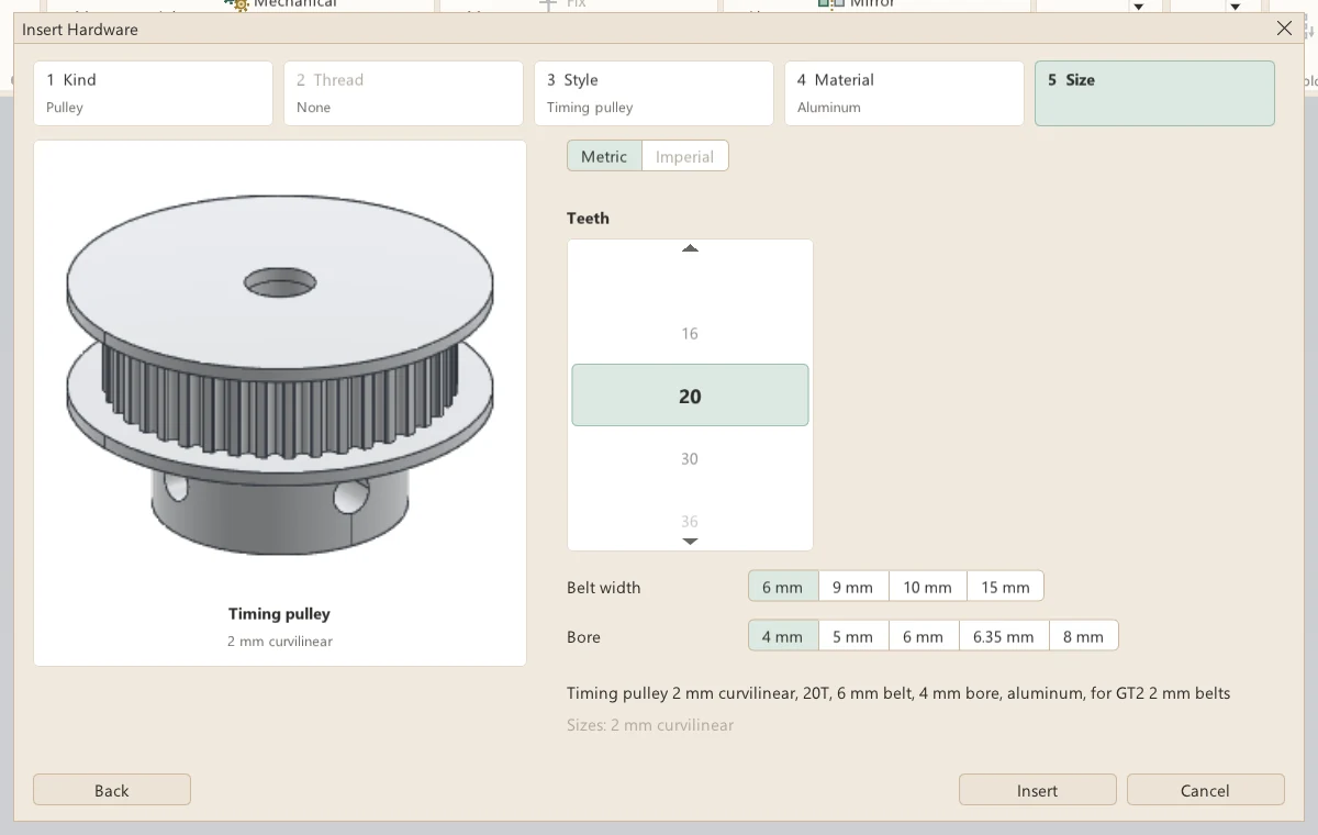
A piece is chosen in steps of large pictures: its kind, a cosmetic or modeled thread, its style, its material and its size. The graphics window stays live while the steps are open, so a hole or a plate can be measured to choose the size.
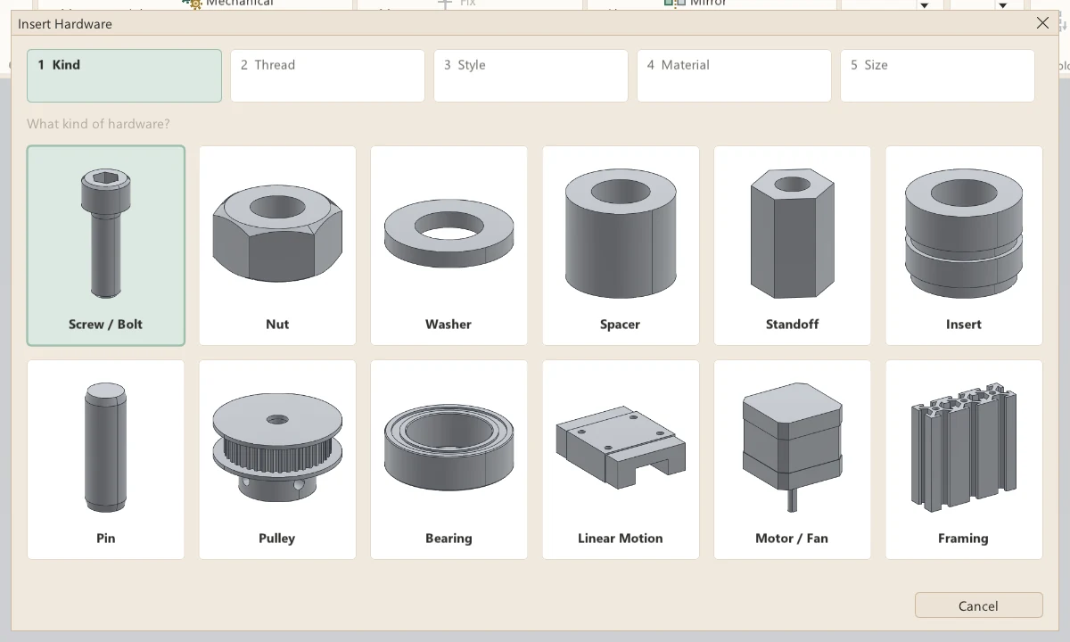
- Styles grouped under headings, such as Socket screws, Bolts, Machine screws and Set screws
- Metric or Inch, and the size on rolling wheels: the mouse wheel over it, a drag up or down, or a click on a size
- A screw's diameter and length on two wheels, with its pitch and a partial or full thread
- Lengths typed for threaded rod, shafts, rails, lead screws, extrusion, keys and spacers
- A pulley's belt width and bore chosen beside its teeth
- Insert as Part or Assembly, for hardware with moving parts
- A click on the model while the steps are open measures it, such as a hole's diameter
Placing
Every piece sits on its own top plane with its axis along its own Z, so each kind is placed the same way, by the hole, face or rail it goes on. Placing goes on, piece after piece, until Esc.
- One click on a hole's edge seats a screw, nut, washer, bearing, pulley or insert there, concentric with the hole and on the face beside it
- Or two clicks: the round wall of a hole or of a pin for the axis, then the surface, edge or point it sits on
- Turn: Flip turns the last piece over on what it sits on
- A washer clicked onto a placed screw or nut goes under its head, the screw lifted onto it
- Rails, extrusion, T-slot nuts, brackets, keys, upright shaft supports and the blower go on a flat face in one click, free to slide along it
- On a library extrusion's side, a piece goes on the nearest slot's middle, along the slot
- A rail carriage clicked onto a library rail of its size slides along the rail and nothing else
- Each piece one undo step
- Pattern Driven puts a copy of a placed screw in every hole of the part's own hole pattern
Hardware as assemblies
Fourteen families with moving parts can go in as an assembly of their real parts instead of one part, the parts that turn on revolute joints of their own. The assembly sits on the same top plane and axis as the part, so one can be changed for the other without its mates losing their references.
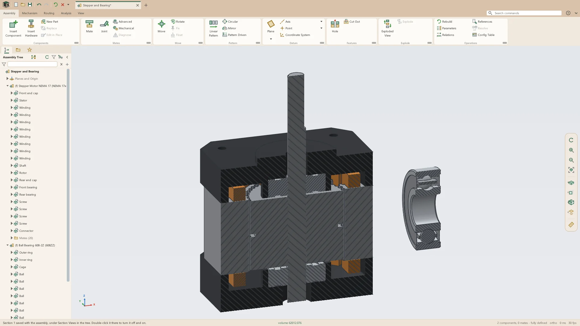
- Six ball bearing families: the outer ring, the inner ring and cage on revolute joints, the balls, and shields or seals
- Stepper motors: end caps, stator, eight windings, the shaft and its 50-tooth rotor on a revolute joint, two bearings, four screws, and the connector socket on NEMA 17 and 23
- Toothed and smooth idlers: two bearings, and the body turning on them
- Linear ball bushings: sleeve, retainer, balls and seals
- Rail carriages, standard and long: block, end caps, seals and balls
- Axial fans and the radial blower: the frame or housing, and the impeller on a revolute joint
- One assembly file for each family, each size a configuration of it
- Counted as one item in every bill of materials, its rings and balls never listed
Change Hardware
Change Hardware, on the right-click menu of a placed piece, opens the steps at the style for the hardware selected and changes it to another style, material or size of the same kind. Its mates stay, and any that cannot find their references on the new piece are shown in red.
- Several pieces of one kind changed at once
- A screw changed to another length or head style, its axis and seat mates kept
- A part version changed to its assembly version, and back
- Also found by name in the command search
Threads
A threaded piece is drawn with a cosmetic thread by default, a tinted threaded length on a plain cylinder, or with its helical thread modeled. Each piece keeps the way it was inserted, and Assembly Properties can set every piece at once.
- Cosmetic or modeled chosen in the thread step, with a picture of each
- Cosmetic: a plain cylinder, quick for assemblies of many pieces
- Modeled: the helical thread itself, heavier
- Assembly Properties, Hardware Threads: As Inserted, Cosmetic or Modeled
- Modeled for every piece asks first, as it can slow a large assembly down a great deal
- Both versions made together when a piece is inserted, so switching builds nothing
- One bill of materials line for a size whether its thread is cosmetic or modeled
See it on your own parts
Beta builds go out by email. Say what you design and what you use now.