 Leta
GD&T and annotation
Everything on the Annotate tab stands on the model's own edges, named the way the part names them, so dimensions, callouts and symbols follow the model when it changes. Anything that can no longer find its edge is shown in red and listed, never moved to another edge without saying so.
The Dimension tool
One tool (D) measures what is picked: an edge for its length, a circle for its diameter, an arc for its radius, or two edges or points for the distance or angle between them. Where the text is put decides whether it reads horizontal, vertical or aligned, as in the sketcher.
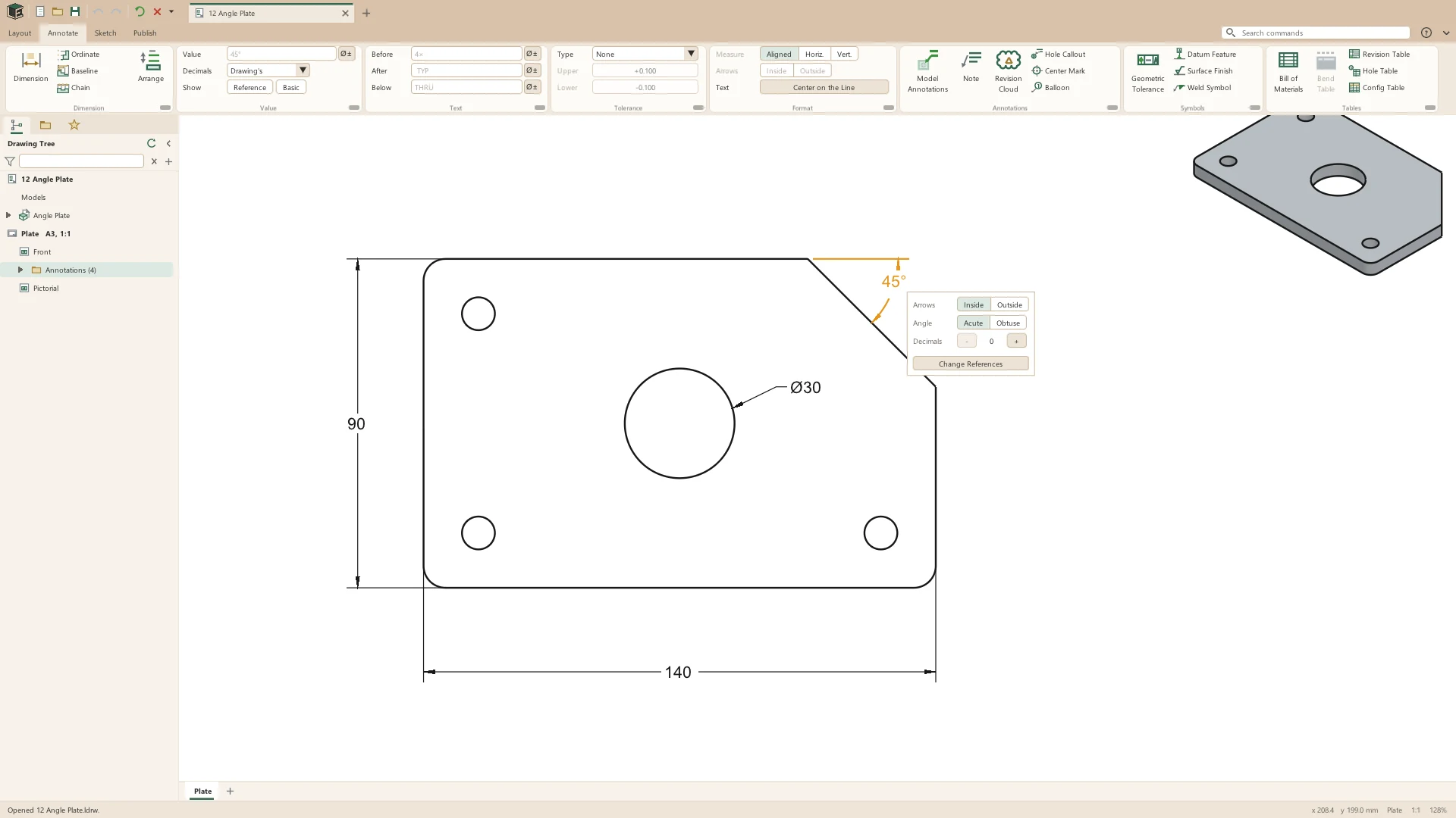
- Lengths, diameters, radii, distances and angles from the one tool
- A ball's outline dimensioned SØ, and a cone's sides taken as straight edges
- The center of mass marked on a view and dimensioned to
- In pictorial views, the model's true sizes by default, or what the paper shows with As Drawn
- A click on a dimension opens a menu beside it: arrows inside or outside, an angle acute or obtuse, decimals 0 to 4, and Change References
- Where each end of a distance meets a circle: its center, its near side or its far side
- An angle keeps the corner it was placed in wherever its text is dragged
- The value written over, text before, after and under it, and a palette of drafting symbols
- Lines sketched on a view dimensioned like the view's own
- Each view's dimensions, notes, symbols and balloons grouped under it in the drawing tree, and turned with it when the view is turned
Ordinate, baseline and chain
Ordinate, baseline and chain dimensions place a whole set from one click per feature, each with a preview. Arrange then spaces the dimensions of the selected views, or the whole sheet, in rows outside each view.
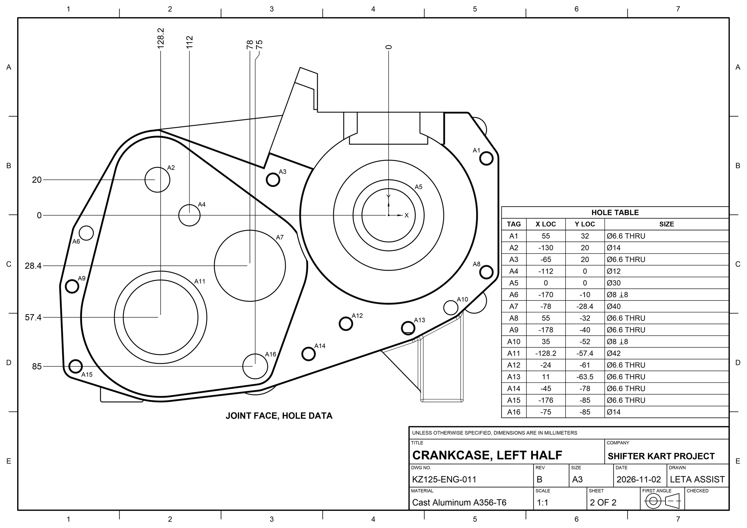
- Ordinate: the zero, where the values go, then each feature; each value at the end of a line straight out from its feature
- An ordinate value moved along its row is reached by a jog
- Baseline: every dimension from one base, each a row further out
- Chain: dimensions end to end along one line
- A circle picked means its center, and a line picked near an end means that end
- Arrange: the shortest nearest the view, the first row 10 mm out and each next 8 mm on
- Dimensions that do not overlap share a row, and values are centered between their extension lines
- Each ordinate set on its own row, its values clear of each other
- Radii, diameters, angles and aligned dimensions left where they are
- Arranging twice moves nothing, and each Arrange is one undo step
Tolerances
A selected dimension's tolerance is set in the ribbon's Tolerance group, and several selected dimensions take it together.
- Symmetric: one amount, ±
- Plus / Minus: an upper and a lower amount
- Limits: the two limits written out
- Basic: the value boxed, for a geometric tolerance to be measured from
- Reference dimensions, written in parentheses
- Text before the value, such as 4×, after it, such as TYP, and a second line under it, such as THRU
Model annotations
Model Annotations puts on the selected views, or every view of the sheet, what the model says of itself: each hole's and thread's callout and center mark, each chamfer's callout and each round's radius, each once. Hole Callout places one of them by hand, with a leader to its edge.
- Hole callouts with the count, size, depth, counterbore or countersink, and thread
- Chamfer callouts such as 1 × 45°, round radii such as R5, and TYP when one feature has several edges
- Callouts read their feature each time the sheet is drawn, so they change with it
- A callout edited to other text becomes an ordinary note
- Center marks on circles and arcs
- Tapped holes and threads drawn by convention: a thin three-quarter circle end on, two thin lines from the side
- Modeled threads drawn plain, without their helices, so their views are quick to work out
- Thread callouts such as M6x1 ↧12 into a hole, or M6x1 × 12 LONG along a shaft
- A printed thread called out with its clearance: PRINT CLEARANCE 0.15 (FDM NORMAL)
Notes and leaders
A note goes on the sheet, or on a view with a leader to an edge, and then moves and turns with the view.
- Text height, bold, and lines left, centered or right
- Leaders ending in an arrow, an open arrow, a dot, a slash or nothing
- Several leaders on one note
- A click on a leader offers Split, which puts a bend in it to drag, Add Leader, Change Reference and Delete Leader
- The leader's straight run out of the text set in the note or dragged at its knee
- Dimensions, notes, symbols, center marks and balloons put on layers, each layer with its color and line weight, shown or hidden
Balloons and revision clouds
A balloon names a part of an assembly by its item number in the bill of materials. A revision cloud rings what a revision changed.
- Balloon numbers read from the bill of materials, with a leader to the part
- A balloon on a part inside a sub-assembly finds the sub-assembly's row when it is listed as one item
- Revision Cloud on the Annotate and Sketch tabs: the corners clicked, then the first again or Enter
- The width of the cloud's arcs set in the strip, 5 mm to start
- A cloud drawn on a view moves with it
- A revision table that hands out the next letter as the standard counts them, I, O, Q, S, X and Z skipped, dated today
- The title block's REV follows the revision table's last row
Geometric tolerances
Geometric Tolerance places a feature control frame, to ASME Y14.5 or ISO 1101, with a leader to the edge it controls. Its editor shows each change on the sheet as it is typed.
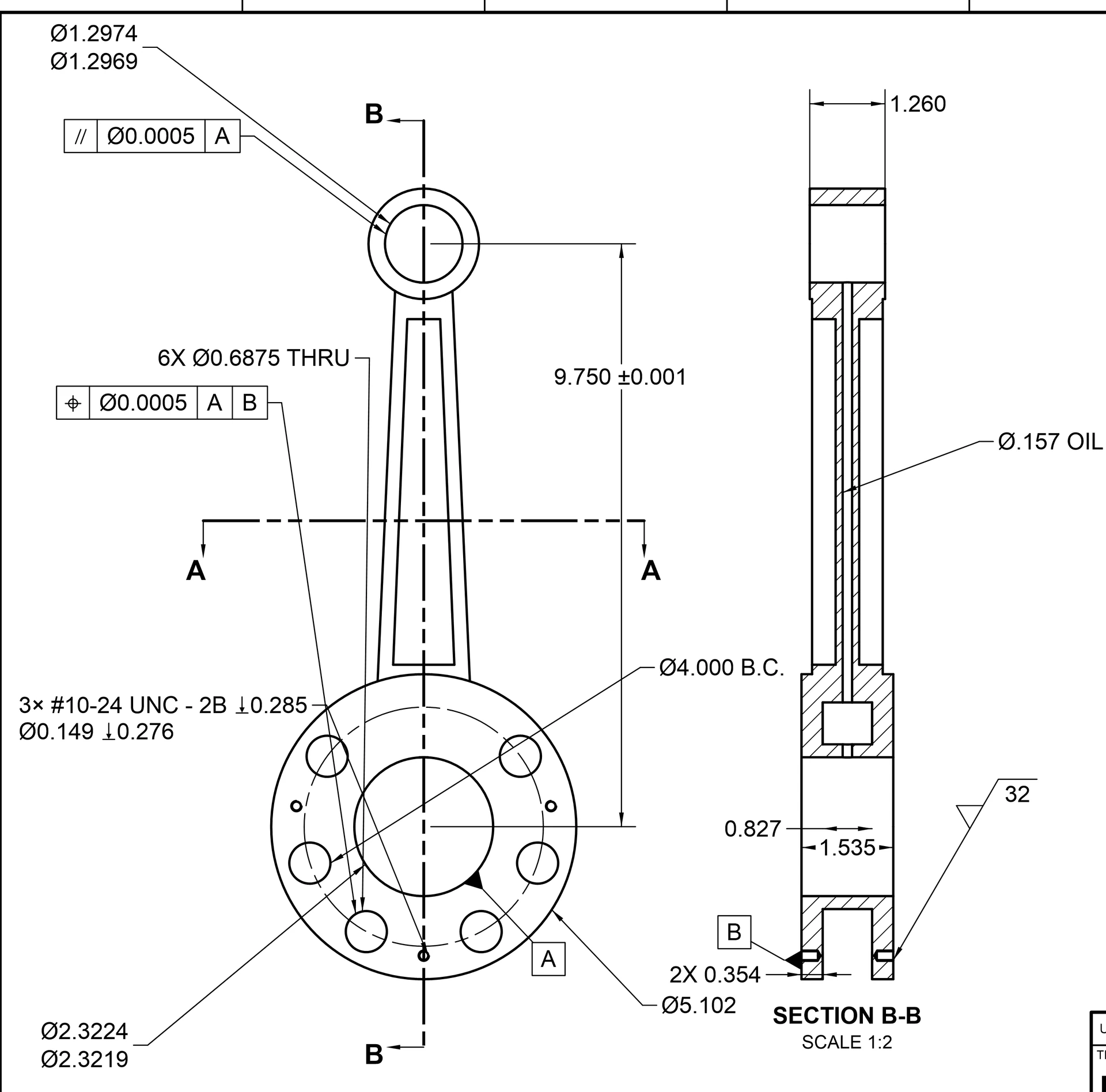
- All fourteen characteristics: straightness, flatness, circularity, cylindricity, profile of a line, profile of a surface, angularity, perpendicularity, parallelism, position, concentricity, symmetry, circular runout and total runout
- A diameter zone, and the tolerance
- Material conditions and modifiers: MMC, LMC, RFS, projected tolerance zone, free state, tangent plane and unequally disposed
- Primary, secondary and tertiary datums
- Composite frames of two rows
- Text over and under the frame, such as 2×
- A frame on a view follows its edge as the model changes, or stands free on the sheet
- The last frame's settings carried to the next
Datum features
Datum Feature stands a datum's letter, boxed, on a filled triangle on the feature's edge: the edge is clicked, then where the letter goes.
- The next unused letter handed out, I, O and Q skipped
- The triangle square to its edge, on the box's side
- The letter changed in the symbol's editor
- On a view's edges, a flat pattern's edges and the lines a section cuts
Surface finish and weld symbols
Surface finish symbols follow ISO 1302 and weld symbols AWS A2.4. Each stands on its edge or on a leader to it, and follows the model.
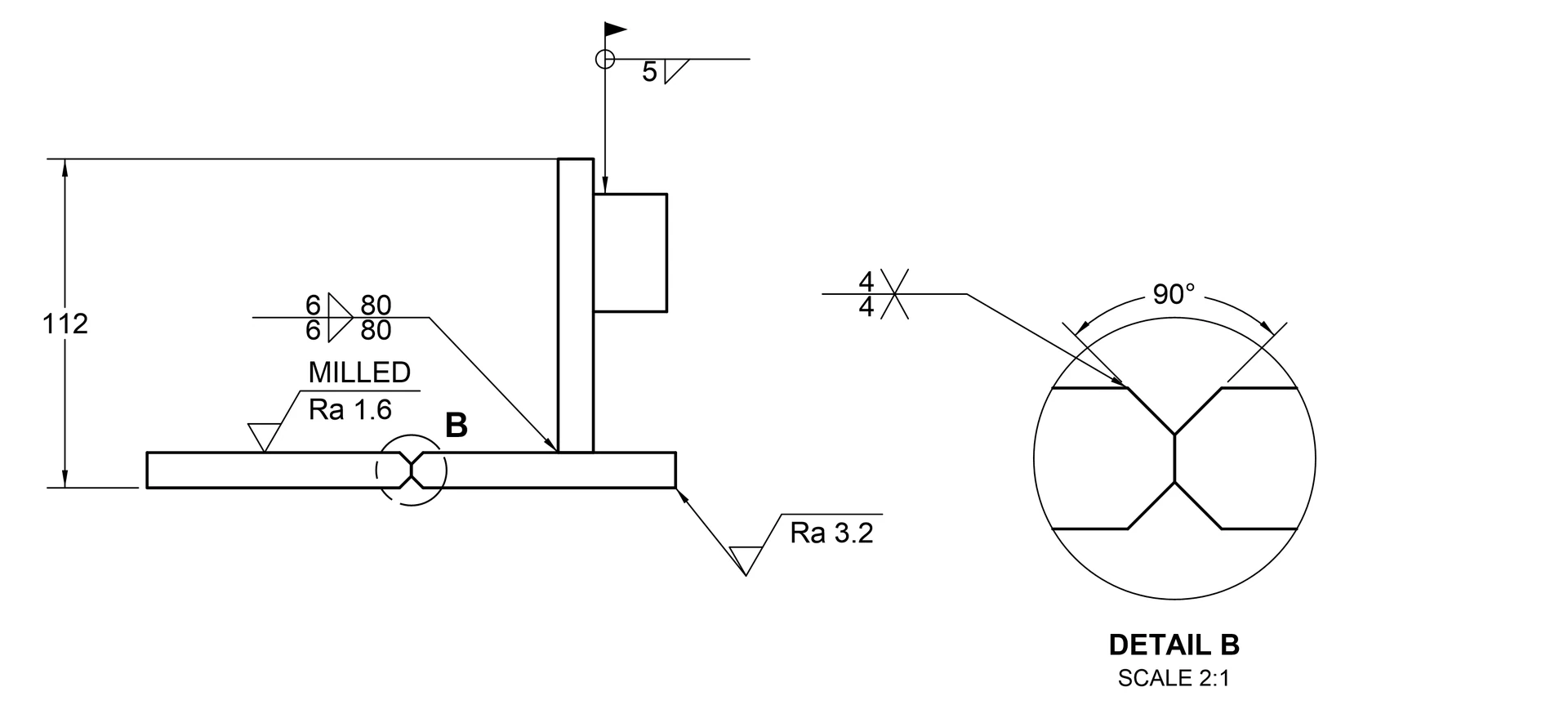
- Finish made any way, by removing material (a bar) or without removing it (a circle)
- Roughness typed or picked from Ra 0.4 to Ra 25
- The method over the long leg, and the lay: parallel, perpendicular, crossed, multidirectional, circular, radial or particulate
- All around the outline
- Clicked onto its edge it stands there; placed away from it, it gets a leader
- Welds: fillet, square groove, V groove, bevel groove, U groove, J groove, plug or slot, spot and seam
- On the arrow side, the other side or both
- Size to the left, length or pitch to the right, an all-around circle and a field weld flag
- The tail's fork with a process or a note
On section lines
The lines a section cuts are not edges of the part, so Leta finds the face each one comes from. Dimensions, notes, callouts and symbols attach to them and stay on them when the part changes.
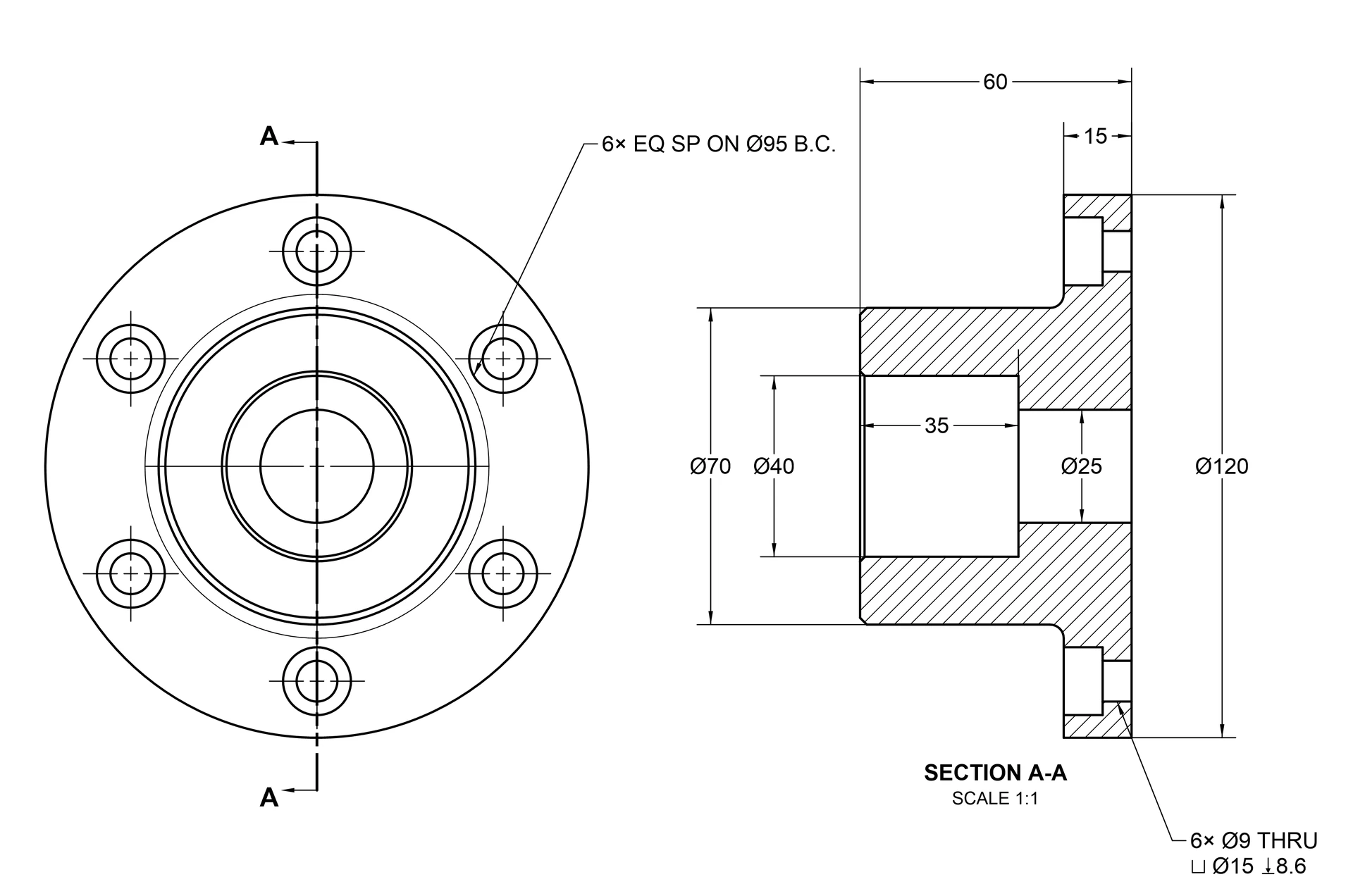
- On section views, and on views cut in place by a plane or a sketch
- A bore cut along its axis gives two lines, each found again on its own
- Nothing reported lost while the view's lines are still being worked out
Lost references
Leta reads a part again when its file changes, and every view, dimension and note follows. An annotation whose edge is gone is drawn as a red question mark where its text stood and listed as lost, never dropped or moved to another edge.
- A part saved with changes is read again and its views redrawn, with no need to reopen the drawing
- A lost dimension reads (lost) in the drawing tree
- A callout whose feature is deleted or suppressed listed as lost
- An export or print says how many annotations could not find their edges, and which views could not be drawn
- Change References puts a dimension on new edges, keeping its decimals, text, tolerance and arrows
- Annotations made on a flat pattern view lost while the view is folded, and found again when it is laid flat
- A view that cannot be drawn says so on the sheet, with its reason under the pointer
See it on your own parts
Beta builds go out by email. Say what you design and what you use now.