 Leta
Parameters and configurations
Named values, the rules between them and the sizes a design comes in are kept in the part or assembly and edited in tables. Any number of any feature can be a parameter or an expression, and project parameter files share values across many parts and assemblies.
Parameters
Parameters is a table of the part's named values, with the system's own beside them. Model Intent on the Tools tab opens it, with Relations and Config Table, and so does the part's row at the top of the model tree.
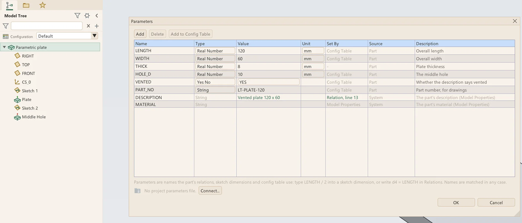
- Types: Real Number, Integer, String and Yes No, with a unit for lengths and angles
- Set By and Source say what gives each value: the part, a relation, the Config Table or a project file
- System parameters: DESCRIPTION, MATERIAL, CONFIGURATION, and a sheet-metal part's SMT_THICKNESS, SMT_BEND_RADIUS and SMT_K_FACTOR
- Mass properties as read-only parameters: MP_MASS, MP_VOLUME, MP_SURFACE_AREA and MP_CG_X, Y and Z, kept in the part file for each configuration
- Names match whatever their case: LENGTH, Length and length are one name
- A title block field falls back to a parameter of the same name, such as PART_NO
- A parameter's right-click menu: Delete, Add to Config Table
- Assemblies have parameters of their own, of the same four types
Relations
Relations is a program of lines that set dimensions, feature values and parameters from one another, run top to bottom at every rebuild. Verify works the text out without keeping it, and the Results tab shows what each line set and to what.
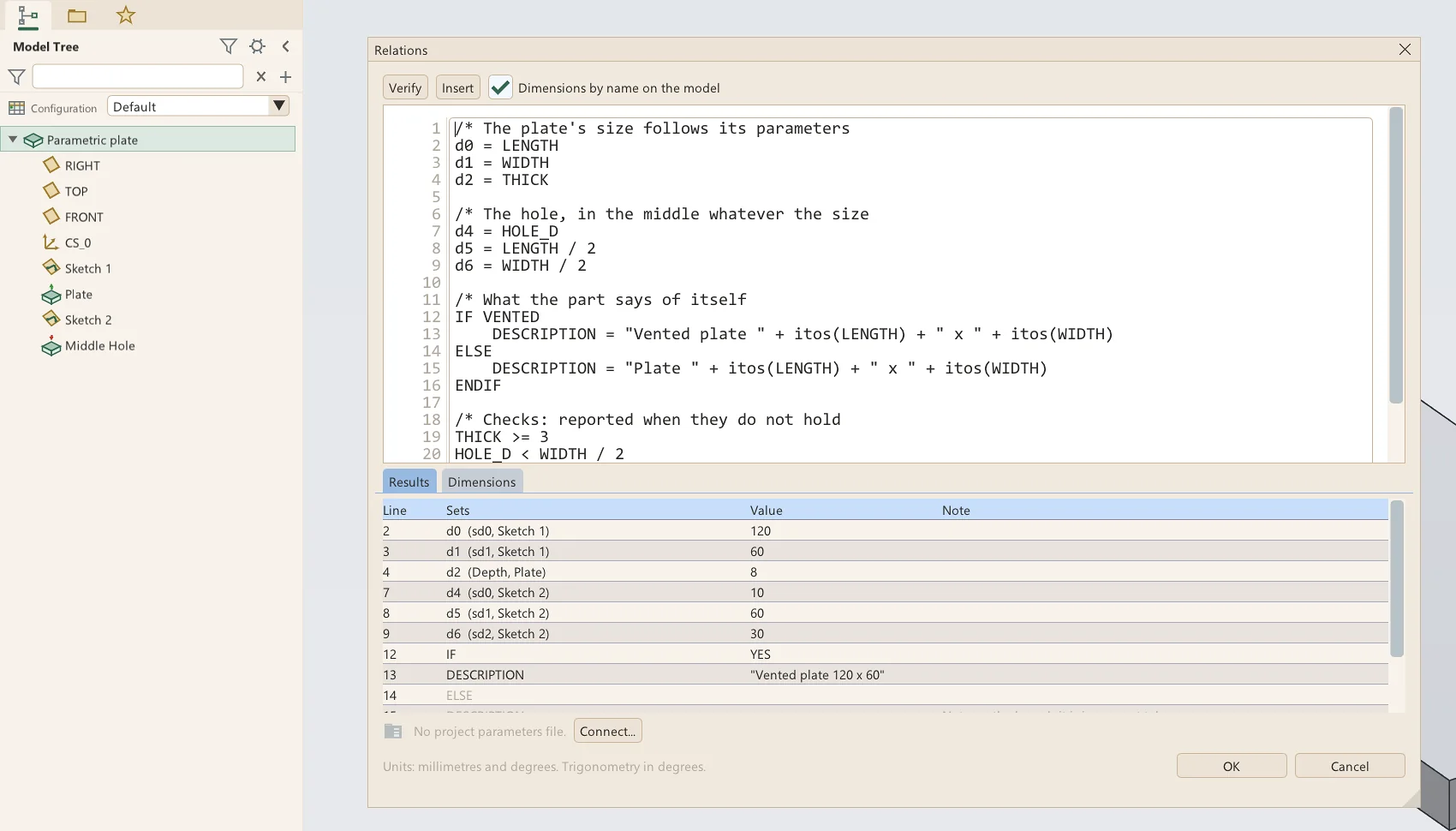
- Values with units: mm, cm, m, in, ft, deg and rad
- IF, ELSE and ENDIF, nested
- Functions: sin, cos, tan, sqrt, abs, floor, ceil, round, min, max, mod, if(), and text functions such as upper and rtos
- Check lines such as d4 < 200, reported in red when they do not hold
- Insert: a parameter, a dimension by feature, a function, an operator, an IF block or a comment
- A value a relation sets is shown as set by it and is not edited by hand
- A relation that sets a name the part does not have offers to add it as a parameter
- Assemblies have relations too, reading their parameters and their mates' values
Dimension symbols
Every dimension of the part has a symbol, d0, d1 and on, that stays with it for good. Renamed, say LENGTH for d0, the new name follows into every relation and expression that reads it.
- Symbols for sketch dimensions and every feature's numbers alike
- While Relations is open, a click on a feature in the tree shows its dimensions on the model by symbol, and a click on one inserts it
- The Dimensions tab lists every dimension: its symbol, whose it is, its value and what sets it
- A middle-click on a feature in the tree shows its dimensions on the model, ready to edit
Expressions in every value
Every number of a feature, a hole, a datum, a pattern, a sheet-metal rule, and an assembly's mates and joints can be a number with units, a parameter or an expression, kept as written. A double-click or Ctrl+click types into a field, and a drag across it changes its value.
- Names offered in a list as a word is typed; Tab or a click finishes it
- A field holding an expression shows = and a green edge, with the expression in its tooltip
- One that cannot be worked out shows a red ! and the reason
- Expressions that read each other in a circle turn red and say which reads which
- One source for each number: a relation, a Config Table column or an expression, never two
- Sketch dimensions take expressions over the sketch's other dimensions and the part's names
- Units typed with the value: 1/2 in is 12.7 mm
- Locked dimensions refuse a change until unlocked
Config tables
A Config Table holds the configurations a part comes in: a row each, the Default first, and a column for each thing that varies. Every configuration is built from the Default and never changes it, and an edit made in another configuration stays in that one.
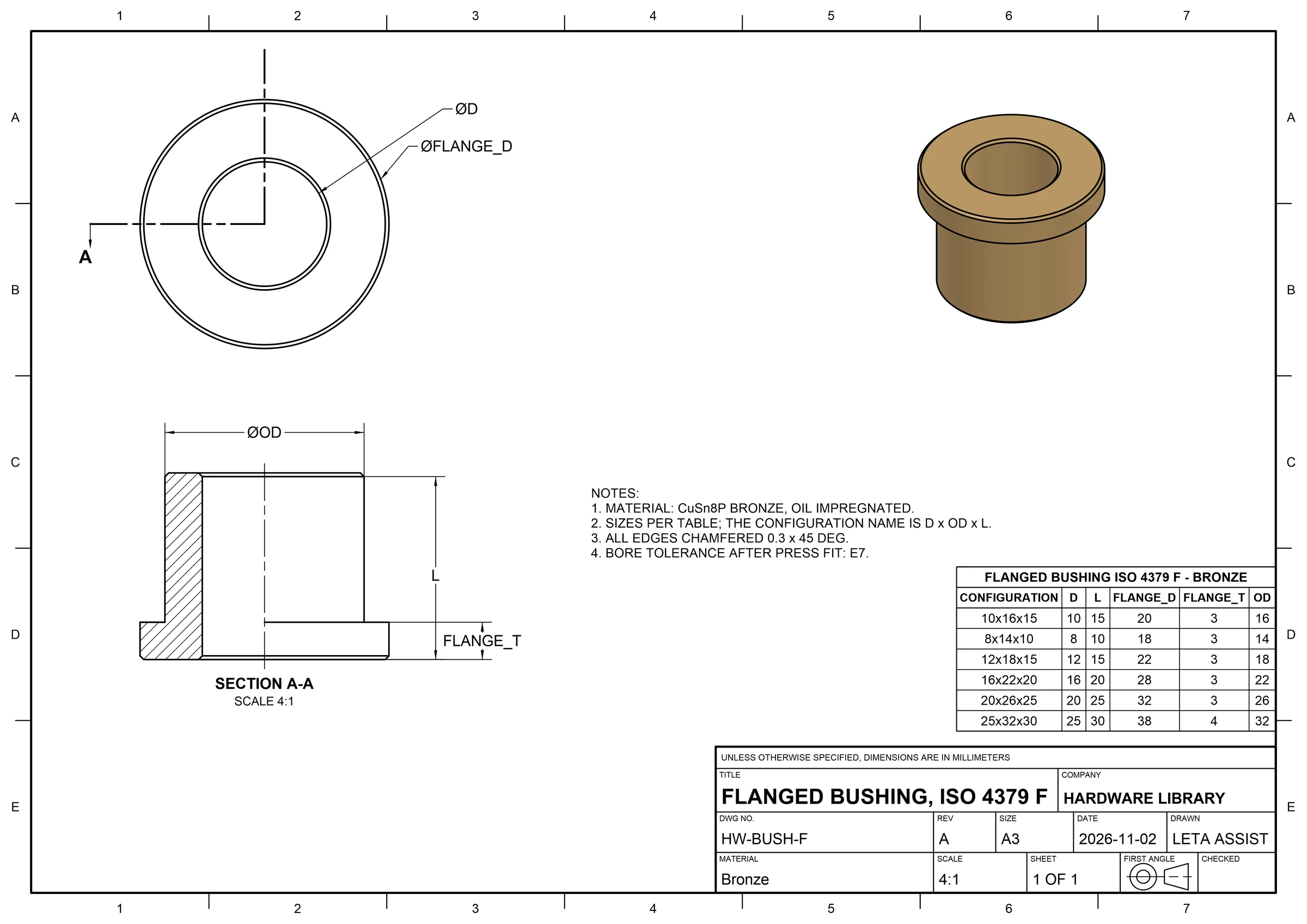
- Columns for dimensions, parameters, whether a feature is built, and the description
- Cells marked * follow the Default
- The Configuration box at the top of the model tree switches configurations, and the title reads Part<Config>
- Add, Copy, Delete and reorder configurations; Add to Config Table from a feature's or a parameter's right-click menu
- A feature left out of a configuration leaves out everything built on it
- Check All builds every configuration and says which fail and why
- Export and Import CSV
- Drawing views show any configuration, so two can stand side by side on one sheet, and a bill of materials counts each as a part of its own
Assembly config tables
An assembly has a Config Table as a part has, with columns for what an assembly can vary, from which parts are in it to which file each one is. Switching back to a configuration puts each swapped part's mate references back exactly.
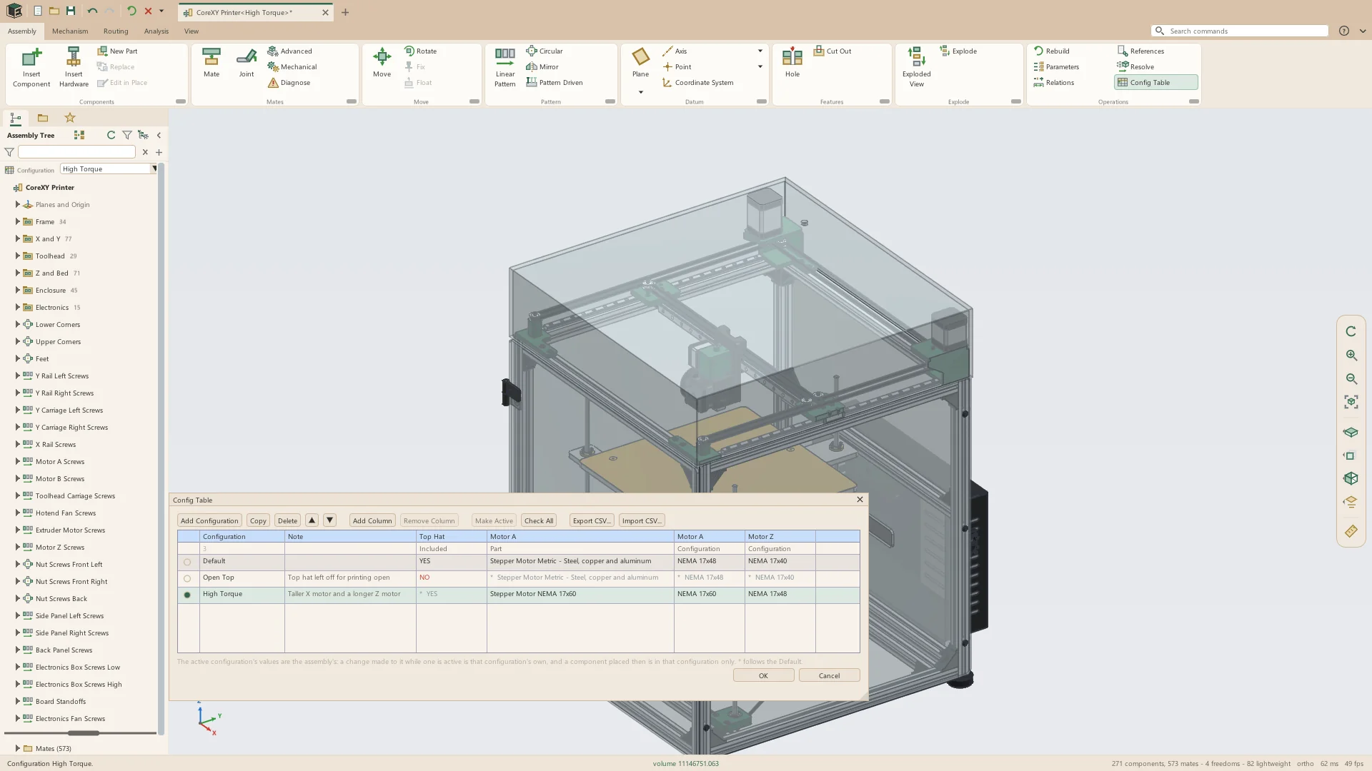
- Components included or left out, and the configuration of its part each one uses
- Part columns: a component's file swapped for alternates, configuration by configuration
- Mate and joint values, and whether a mate is used
- Pattern copies and spacing, assembly holes' diameter and depth, parameters, description and part number
- Fill by Row Names picks each part's configuration of the same name
- Sub-assemblies placed in a configuration, listed in the bill of materials as Frame<Long>
- Insert Component asks which configuration to place
- Deleting in another configuration offers to suppress it there instead
- Annotate > Tables > Config Table puts a part's or an assembly's configurations on a drawing sheet
Project parameter files
A project parameter file (.lppm) holds values and options that many parts and assemblies share. It opens in a smaller window of its own, and the parts connected to it follow it while they are open.
- File > New > Project Parameters
- Parameters with a type, unit, value, group and description; Add, Duplicate, Delete, Move Up and Move Down
- Units of its own: lengths in mm, cm, m, in or ft and angles in degrees or radians, kept in the file in mm and degrees, so each part reads them in its own units
- Import and Export CSV in the file's units, and Where Used to find the parts connected to it
- Options: the hole standard new holes start in, a material for parts with none, and the drawing template new drawings start from
- Connected from Parameters or Relations: Connect, Open, Disconnect
- Read only in a part, and kept with it, so the part builds without the file
- Connected parts and assemblies follow the file while open, checked once a second
- Project Sets: named sets of values; an assembly shown in a set builds every part connected to that project with that set's values
See it on your own parts
Beta builds go out by email. Say what you design and what you use now.