 Leta
Holes and threads
Hole drills standard holes at sketched points, sized from ISO metric and ANSI inch tables, with tapped threads shown cosmetically or cut into the wall. Thread puts a modeled thread on any cylinder, a shaft's or a hole's, in fourteen standards, and opens it up by a set clearance for parts that will be 3D printed.
Hole
Hole makes six kinds of hole, each sized from its standard's table, so changing M6 to M8 changes every diameter and depth that follows from it. A diameter typed by hand makes a hole of its own size.
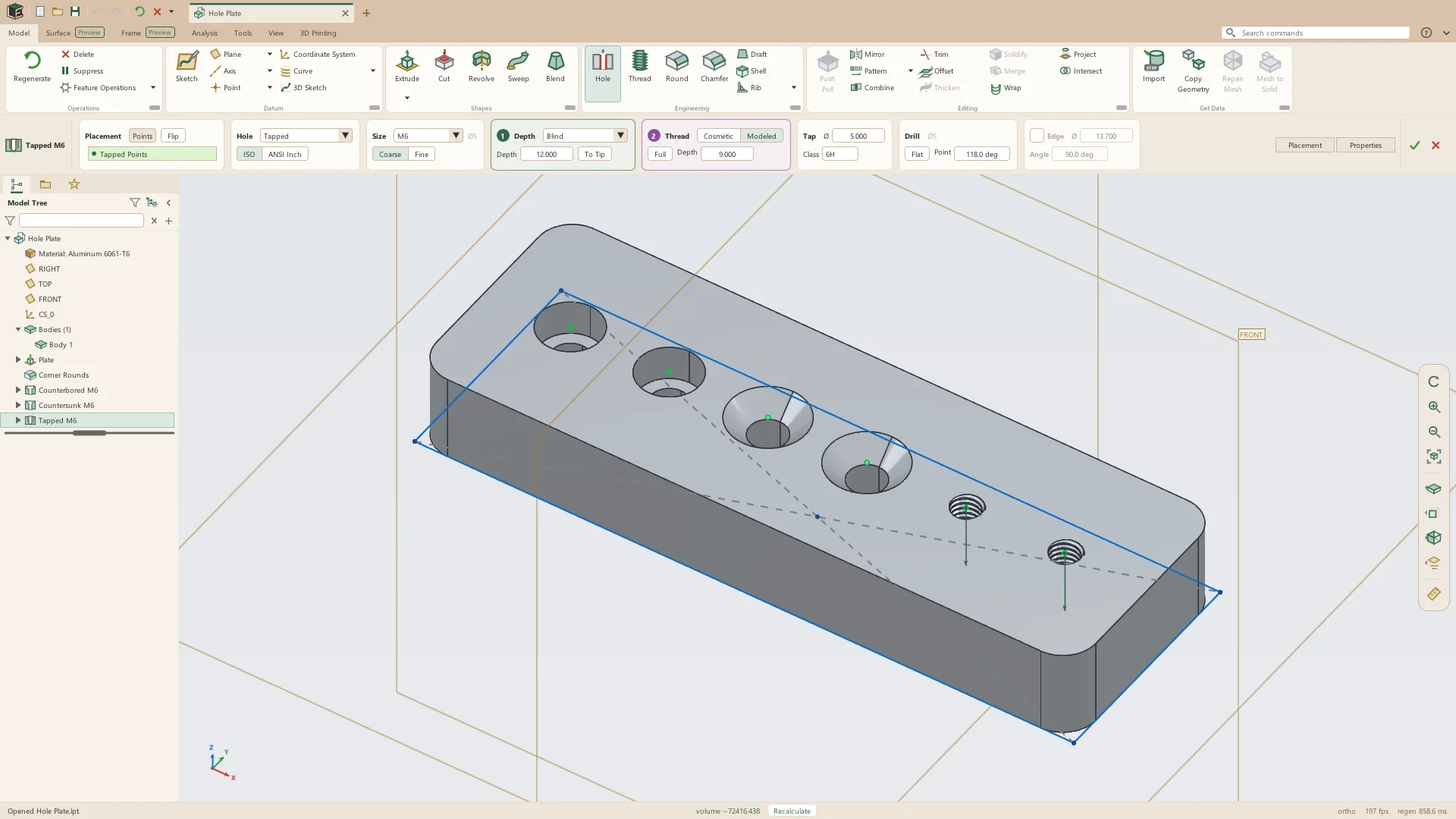
- Simple, Counterbore, Countersink, Counterdrill, Tapped and Tapered
- ISO metric sizes M1.6 to M64, and ANSI inch sizes #0 to 1-1/2
- Clearance holes in Close, Normal and Loose fits, after ISO 273 and ASME B18.2.8
- Counterbores sized for socket head cap screws, and countersinks for flat heads: 90° for ISO, 82° for inch
- Tapped holes in coarse or fine pitch (UNC or UNF in inch), drilled at the tap drill
- Tapered holes narrowing by an included angle, as for a taper pin
- Edge: a countersink on the top edge of a simple or tapped hole
- The standard new holes start in is set in Options, or by a project parameter file
- Every diameter, depth and angle can be a parameter or an expression
Depth and drill point
A hole ends at a depth, at the next face it meets, at a chosen face or point, or runs through the part. A blind hole ends on a drill point, or flat as an end mill leaves it.
- Blind, Through All, Up To Next and Up To Surface
- Up To Surface ends at a flat face, a datum plane, a vertex or a sketch point
- A blind depth measured to the drill point's shoulder, or with To Tip to its tip
- A drill point of 118°, or any angle from 60° to 179°, or Flat
Placement
A hole is drilled at every sketched point of its placement, square to the sketch and into the material. Pick a face and Points opens a sketch on it to click and dimension the holes, or hand it a sketch of points made before.
- A face or datum plane picked: Points sketches the holes there, and that sketch stays under the hole in the tree
- A whole sketch: a hole at each of its sketched points, and none at construction centers
- Single points picked from shown sketches: endpoints, corners, centers and sketched points
- Flip drills the other way from the placement
- Holes patterned and mirrored as features
- A hole whose point no longer lies on the part is shown in the caution color and reported, rather than drilled with nothing said
Tapped holes
A tapped hole's thread is cosmetic, drilled at the tap size and drawn as a thread with nothing cut, which is quick to build; or modeled, cut into the wall as the helix it is, for a part that will be printed.
- Cosmetic or Modeled, chosen in the Thread card
- Threaded the full depth, or to a thread depth of its own
- The tap drill from the table, shown in the Tap card
- A tolerance class written in the callout: 6H, 2B
- Modeled threads through all, blind, or part way down a through hole
- A modeled thread runs only as far as the part reaches
Thread
Thread makes a modeled thread on any whole cylinder of the part, a shaft's, a boss's or a hole's. It is on the ribbon after Hole, and on the card a click on a cylinder brings up, as Round and Chamfer are on an edge's card.
- Fourteen standards: ISO Metric, ISO Metric Fine, UNC, UNF, UNEF, Trapezoidal, ACME, Buttress, Whitworth (BSW), BSP (G), BSPT (R), NPT, Square and Custom
- Sizes from each standard's table: M1 to M68 coarse, #1-64 to 2-4.5 UNC, G1/16 to G6, NPT 1/16-27 to 6-8, and lead screws such as Tr8x8(P2)
- A new thread is sized for the cylinder clicked: the standard from the part's units, the nearest size, the whole length, and the start at an open end
- A shaft drawn at its nominal size, or a hole drawn at its nominal size or at the tap drill, comes out the standard thread
- Right or left hand, and several starts, with the lead shown
- The full cylinder, or a length from an offset; Flip starts it from the other end
- Lead-ins: a 45° chamfer at the start, the end, or both
- Taper pipe threads (BSPT, NPT) narrow 1 in 16 on the diameter
- Custom: the flank angle and depth typed; a 90° form prints with 45° overhangs
- A cross hole through a thread stays open
Print fit
Printed threads come out tight, since outer surfaces print wide and holes print narrow. Print Fit sets every surface of the thread a clearance off where its mate's would be, so a printed bolt and a printed nut each take their own.
- Standard: as the standard makes it, for machined or bought parts
- Resin Print: 0.05 mm, for SLA and MSLA prints
- FDM Tight: 0.10 mm, from a well-tuned printer with a 0.4 mm nozzle
- FDM Normal: 0.15 mm, a fit that turns by hand
- FDM Loose: 0.25 mm, for prints that come out wide or thick layers
- Custom: any clearance typed, such as one found by printing a test pair
- The clearance, diameter, pitch, length and offset take parameters and expressions
Drawings and assemblies
Drawings read holes and threads from the model, so their callouts and tables follow the part when it changes. In an assembly, holes go through several parts at once, and a part can be held by its mounting holes.
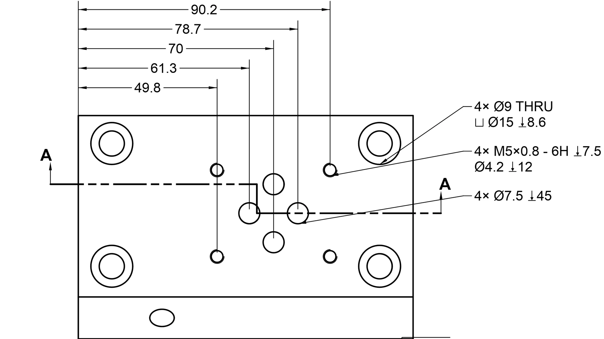
- Hole Callout writes the count, size, depth, counterbore, countersink and thread: 4× Ø6.6 THRU
- Model Annotations calls out every hole and thread in a view
- Threads drawn by convention: thin lines at the root, and a three-quarter circle end on
- A printed thread's callout gives its clearance: PRINT CLEARANCE 0.15 (FDM NORMAL)
- Hole tables: each hole tagged A1, A2 and on, with its X, Y and size
- An assembly's Hole drills through several parts at once, kept in the assembly unless Also Cut the Parts is ticked
- The Hole Pattern mate holds a part by a hole and a second hole that lines up
See it on your own parts
Beta builds go out by email. Say what you design and what you use now.